Electron Engine ™
Printed Circuit Boards by Emissionlabs ®
EE20 Gold Plated Multi Purpose Board. Version 2.9
 Introduction (You are here)
Introduction
Can be used with LL1544, 1544A, 1545, 1545A, 1550, 1636, 1678, 9206, 9226, 9226XL.
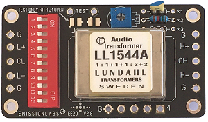 The connections of the popular input transformer LL1544A, and many MC transformers is the same. A universal board was made, which offers the data sheet possibilities, and in addition a few NEW options as well, all programmed by the 12 position piano switch.
For the above, order the transformer of your choice with Option1.
You receive the transformer, the PCB, the switch and mounting hardware.
The gain switch board EE22 is not included (see below) but can be added later. Besides all gain options are possible anyway.
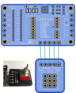
Same EE20 Board, with external switch board EE22 connected. All options stay working, but in addition you can choose two gain factors (of your choice) with the external switch.For instance with LL1544a set the piano switch, such that the gain is 4x. With the external switch you get then 2x or 4x.
Or change the setting of the piano switch to get a gain of 1x. Then with the external switch it gives 1x or 2x.
For the above, order the transformer of your choice with Option2.
You receive the transformer, the PCB, the switch, mounting hardware, the switch board EE22, and the special switch (with silver plated contacts).
Dimensions:
- PCB: 70 x 40mm
- Position of Screw Hole centers: 63mm x 32mm. Diameter: 3.5mm
- Vertical space needed: Depending on transformer: 28mm
When designing this board, a matrix switching method was used, and this allows several more alternatives as in the Lundahl data sheet. For hard core audiophiles, the switch could be replaced by wire pieces.
These transformers are almost as old as the Lundahl company itself. You will not be disappointed by the data sheet representing things better as it is. Some other manufacturers drive the transformers on the test bench with zero ohms impedance to get better data. Lundahl always drives them with an impedance, as expected for the application.
So here we come directly to one of the main advantages of Lundahl transformers. If connected the right way, and drive them with the a source impedance not higher as in the data sheet, you are 100% guaranteed to get the performance as they say. You do not know Per Lundahl very well, if you have doubt about this. Many other applications are still possible, and just because it's not in the data sheet, that doesn't mean you can't do it.
I have used Lundahl transformers often myself to upgrade amplifiers with a balanced input, but I was tired of mounting the transformers with glue, and the soldering the tiny pins under a lens. A problem with hand soldering comes when things don't work as expected. It happens to everybody sometimes. Then you will ask yourself, did I make a wiring mistake, or did they send me a bad transformer? But nobody will recognise his own wiring mistake, or grounding error. Also we see it sometimes, people solder a solid copper wire on the pin, and then bend the wire into the right position. If the wire is too thick, this will rotate the pin instead, and internally the fragile windings wire breaks off. Or, a natural thing to do when performance is not good, take an Ohms meter and test all windings for an open connection. Well there is not such a problem! They are all 100% tested. So if the transformer was still good actually, it will now be damaged, unless it is a Mu-Metal core type. Reason for this is, a multi meter works always with 1mA DC test current. They all do! 1000 windings with 1mA has the same effect as 1 winding of 1Ampere. Such current will magnetize the core permanently. Once magnetized, the transformer has a level of distortion, which may not go away. If you don't believe a multi meter pumps 1mA into the circuit, measure the resistance of a blue LED, and you will be surprized about the light output. Or, perhaps you have two multi meters. Set one for 10mA, and measure it's resistance with the other one. You will see, the test current is 1mA!
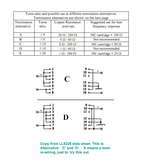
The next problem with hand soldered transformers is this. Suppose it works initially, nobody will touch it any more, just to try out another configuration. This is really a big issue, because this excellent option, to try out the best sounding transfer ratio is lost. Instead of doing it, people avoid it. This was however the INTENTION why this complicated transformer was made this way. (Look here)
Finally there could be some residual hum, because good grounding means sometimes just solder all "ground" wires together, and sometimes it doesn't.
Gain + tuning Options
The gain options + tuning option for the EE20 Board are dazzling, but don't feel confused by this. It is not necessary to use all of this. It is possible to just make just ONE configuration, without tuning, no external components, and no measurements or anything, so just like in the Lundahl data sheet .
The possibilities are as follows:
![]() Options are the same as in the price list.
Options are the same as in the price list.
No Switch used
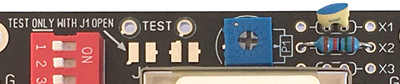
The simplest way would be going by the Lundahl data sheet and create only one single gain factor. It requires only the bare PCB. Wire pieces are mounted instead of the switch. For instance the Lundahl LL9202 data sheet specifies "ALT-E" with a gain of 20x. Suppose you want this. Then look up ALT-E in the table for the switch connections, it will say these: 2, 4, 5, 6, 8, 10, 12. Now just solder wire pieces at those switch numbers, and the board is already finished and working as by the data sheet Option ALT-E. The input is L+ and L-. The output is H+ and H-. The "+" is the same as in the Lundahl data sheet. It is that easy.
OPTION-1
Using the piano switch gives 8 different gain factors, and some other options. Five configurations are from the Lundahl Data sheet (the Alt-... Versions). And three are additional. So set the switches, and the board already works.
OPTION-2
This means adding the external EE22 Switch Board. This very small board attaches to the EE21 Board. Mounting of the EE22 switch is simply by drilling one 6mm hole in the amplifier chassis, and the board os mounted via the switch. The Gain can now be switched between two factors, which by itself can be selected with the piano switch.
The switch settings are given in the next page here. Example: for instance what it sais there in line #8 of the table. A very popular transformer is LL1678 because it can give such high factor of 32x. This is "Alt-E" from the Lundahl data sheet of LL1678. In line #9 it writes: 4, 5, 6, 8, 10, 12, High. This means set the piano switch for 4, 5, 6, 8, 10, 12, and the External switch to the "High" position. Then in the "Low" position it jumps to line #8. So the Switch will change the step up factor from 16 to 32. In case you change your mind about it, just remove board EE22 again,. and one single gain can be set with the piano switch alone. In this case, for instance 32x would be from line #9: 1, 3, 4, 5, 6, 8, 10, 12 (from line #9)
Another use is with Audio Inputs, when using the LL1544A. The data sheet specifies a gain of 1x, 2x or 4x, with different wiring. The EE20 board with LL1544A can do: 0.5x, 0.75x, 1x, 1.5x, 2x, 4x, just by setting the Piano Switch. This is listed in the in the table for the switch connections. If the switch is mounted near to the inputs, it will create a high gain and a low gain input, same as with some very professional amplifiers. If a DIL switch was already mounted, set it to "Off". The same applies for solder jumpers for gain selection of course.
Mounting
There is always a small space where the EE20 board will fit in, it is not much larger than the transformer itself. Just a small hint, but for stereo you could stack two of them on each other with longer space holders. The board has a ground plane, so in case it needs to be mounted inside a wooden box, this is possible. The ground plane is connected to the mounting screws, but a reliable signal ground should be soldered to one of the 'G' connections for this.
Tuning of the EE20 Board
Why is tuning sometimes needed?
All transformers have what is called a self resonance frequency. At this particular frequency, windings inductance and windings capacitance, form an LC-resonator, and you will see the output signal is higher at this frequency only. Normally, the resonance frequency is outside the useful frequency range. So if a particular mains transformer would perhaps resonate at 2000 Hz, it is unimportant, because this frequency is not present anyway. Something similar is with audio transformers. If designed well, the self resonance frequency is above 20kHz, the further above, the better. Yet at some frequency it always takes place, and we can easily filter that frequency out, by adding an RC network at the output. By this we expand the frequency range, eliminate any phase error caused by this, and reduce harmonic distortion.
This resonance will not take place as long as we transfer frequencies below the resonance frequency. However at the edge of a square wave it can become visible with just a few kHz, because such an edge contains higher frequency components (Higher harmonics). With tone transformers of good construction, the resonance frequency is in the range of 30kHz....250kHz, depending on many factors.
Like every resonance, this can be damped, and if done exactly right, this will expand the linear part of the frequency curve. At the same time, the phase error will be less, because amplitude error and phase error always go hand in hand. I would say the phase error counts more, but is harder to measure.
Will it is a lot of talking, but in the end all we need, is an RC Network, or just a low enough resistor across the secondary. For hearing tests, the network it can be switched on and off quickly with a solder bridge. Read more about this.
Changes of Printed circuit Board Version V2.9 vs V2.8
- More space for LL9226-XL
- Gold Plated PCBs