Electron Engine ™
Printed Circuit Boards by Emissionlabs ®
EE20 Gold Plated Multi Purpose Board. Version 2.9
- Audio Board, Applications
 Audio Board, Tuning (You are here)
First of all, tuning is not necessary for all transformers. If needed, this is written in the LUNDAHL data sheet, with recommended values. In you just want to proceed by the data sheet, the EE20 board is prepared for this, just add those parts. Yet already here, it will be interesting to switch on and off the recommended network, to hear any difference.
Generally, moving coil and other applications require a different approach. So below, read only the required part (MC or Audio In/Out).
Tuning a Moving Coil System
This requires three steps.
- The connections of the input / output have to be done right. For this, just set the board to a middle gain, so line #7 of the overview table. This can be changed later. At this point, it is only to check if the system works at all, and if it works free of hum. If not, check the connection scheme. We have made some suggestions here, but feel free to do it another way. Check if the switches are set right, because an invalid combination may result in a humming system.
- Next is to find the best gain. This is extremely tedious when you need to hand-wire the transformers, and few people will be prepared to try out several configurations. This is a pity, because they all sound different, and only one or two will be optimized. The EE20 board however allows you to try those all out, quickly. With the external switch option you are able to switch between two configurations even faster. You may find two configurations sounding nice, and you do want to make a permanent choice. This is what the switch option is intended for. But whatever is the result, the best gain needs to be found
- The final step, is find he best sounding damping factor. This always needs to be done with the Gain that was chosen, and in the likely case two good sounding gain factors are found, take the lowest gain factor for adjusting the damping. Then, the potentiometer P1 is able to cover both gain factors.
Damping of the cartridge needle
The needle has quite a tendency to make unwanted movements by itself. These movements will cause electrical signal, just like any other movement. The result is: the original signal + something additional. This is nothing else but unlinear distortion. If below 5%, it can not be heard as distortion as such, but it becomes rather a specific system sound. Which can actually sound nice if, and it's the magic of tube sound, record players, and transformers.
Or, when distortion is too much, or concentrated on a narrow frequency range, the effect is not good. In this case you will get tired from listening to it, even when distortion is not audible as such. In some cases even then needle jumps out of the groove unexpected during a loud music part, but this is rare. Generally, the longer you can listen to a system without getting tired, the better the system is. Often this is not the same as the first impression, or even opposite. Try listening to a soft distorted guitar sound Santana or Mark Knopfler. It sounds nice, but still 15 minutes is enough of this kind of music for me. Whereas with an acoustical guitar, I can hear it much longer before the ear gets tired.
How is the cartridge damping done?
This is done mechanically by the manufacturer already to some degree. The rest is done by electrical termination, which is just a resistor, absorbing electrical energy, stopping uncontrolled needle movements.
This resistor is mounted at the secondary transformer side, in order to damp transformer resonance as well. The right amount of damping will give optimized mechanical contact between groove and needle. This makes sure, the movement is that of the groove, and not any other.
Please note, we could also apply too much damping. Here comes a difficult situation to understand electrically, but the result is loss of high frequency. (Read the note). From the needle's view, it can be understood that too much damping will also make it difficult for the needle to follow the groove.
All cartridges need individual damping, which the manufacturer describes as "minimum load". This can not be advised in a standard way. So first you just need to know roughly what damping value is needed, and then try it out some values. In the end you will see, the required value is reasonably variable, but it can not be ignored top pay attention to this.
Tuning an Audio Transformer (this is not about Moving Coil)
Here we do not want to damp the signal on purpose, and not create a low impedance on purpose, like we do with Moving Coil. For Audio Inputs, the impedance must only be within a certain range. Nobody would require an amplifier to have exactly 47k Ohms load, and say 20k would be wrong. Even so, too high input impedance will only cause hum sensitivity.
More important is to have no frequency roll off. Not at the high end, and not at the low end of the audio range. Also we want no phase error introduced by the transformer, and no distortion. Ideally, amplifier inputs are balanced. So all together quite some things we would like to have.
I just want to mention briefly, that the stereo information is buried in the phase relation between the left and right channel, and this takes place mostly above 5kHz. So a phase error in the low frequency range is having no effect on this, but in the high range it would damage the spatial effect.
All tone transformers however have something called self resonance. How does this become audible? Coming closer to this frequency, the output signal begins to increase by itself. So when that would happen in the audio range, it would becomes a kind of brightness, because it affects the high frequencies. When this happens, distortion and phase will occur as well. So what would perhaps only be brightness, becomes rather sharpness. It is relatively easy to do something against this. All we need is an extra load, which comes in at the self resonance frequency. And yes, it works that easy. The only thing is, the frequency at which the extra damping begins, must be chosen right. WIth distorting components, as a golden rule, if we prevent the signal to increase in amplitude, also the phase error and distortion will be gone, which is the real reason why we do this. So in order to make this extra load come in right at the resonance frequency, a small resistor is coupled via a small capacitor. This will become effective then, at the resonance frequency. This works simple and good, and it is the RC network you will see in some of the data sheets, in parallel with the output. To make the network adjustable, we can change the resistor.
The data sheet recommends values for this, well chosen by Lundahl. Yet fine tuning can be done as well, to get the upmost out of the transformer. The network can be switched on and off quickly with Jumper J1, to hear the effect, or see in on an oscilloscope.
What will tuning do?
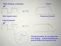
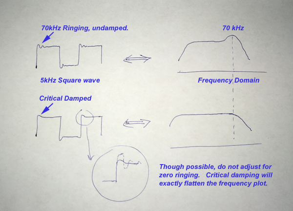
Tuning will give a better linearity and a wider frequency range, though this is outside the audible range. Still it improves the square wave response, in the audible frequency range, which is the reason why it is done. If the square wave response is better, phase error and distortion will be less. As a rule of thumb, if a system will transfer a square wave of a certain frequency, with so called critical overshoot, the system is be able to do a 10x higher sine wave frequency, at a loss of maximum 3dB. So a good square wave response of 2kHz is needed to for a system which can transfer a 20kHz sine wave @-3db. Or if you want a flat response up to 20kHz, test it with a square wave of 4...5kHz. You can (and should) test this for every circuit, tube, transformer. Only if that works, it will apply for the whole amplifier as such.
Self resonance
Having a self resonance point, is something which belongs to every transformer with gain. By good transformer design, this frequency can be pushed far out of the audible range, but at some point it will still occur. This is the cooking recipe of the transformer builder, and each has his own methods. Frankly, do not trust a data sheet which does not specify the self resonance frequency, and how it is measured.
Self resonance means in a practical situation, the output signal will increase by itself when coming closer to this frequency. When this happens, however a phase error gets introduced. Even so, the amplitude does not go up just a little bit, but up to 50%. As long as a sine wave is within the specified frequency range for the product, self resonance will not take place. This is why some transformer manufacturers do not mention this information, simplifying the subject. Yet all transformers have it, and it's a number which stands for good core material and a well designed winding. Reasons are explained below.
If we apply a square wave within the audible range, like 5kHz, this signal contains higher harmonics, some of which may be in the range of the self resonance frequency, and this causes the infamous ringing, even when the signal is the audio frequency. This means at every edge of the square wave, for a very short moment, the transformer resonates. Which means adding of new frequencies, which were not present in the original signal before. At the edge, we see an overshoot of 2...3 periods of the self resonance frequency. I find it difficult to say, if this is a "sound" problem or not. Is looks quite bad to see this in an oscilloscope. But it may become difficult to hear. Still when I hear people saying they can hear the sound of cables, or the better sound of gold plated connectors, I think it is 100x more useful to tune the transformer carefully.
Here is how it is recommended in the LL1544A data sheet.
![]()
The tuning network
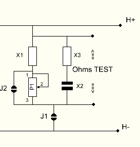 This network is universal, so depending on the use, MC or Audio Input, only some parts are used. Besides, feel free to use it your own way. It is drawn here with a capacitor at the position of X2, just to indicate the most likely use.
- P1 is a variable resistor of PCB type, which probably has not great audio quality. But it is only used for testing. Later it will be shorted by the Jumper J2 and electrically replaced by X1.
- X1, X3, and X3 can be a capacitor or a resistor.
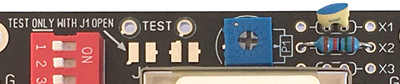
- Jumper J1 has two functions. It switches the network on and off, to check the audible effect. Finally it is used to check with an ohms meter, at what value P1 is set.
- Do not try to measure this with Jumper J1 closed. This may damage the transformer, and besides the measured result is wrong anyway, because the output coil DC resistance is in parallel now.
This little part is all we need.
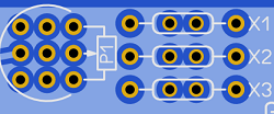
PCB potentiometers have different pin connections and dimensions. With this board lay out, most normal types will fit in.
For adjustment there are a few ways.
Example for LL1544a. (This is not a Moving Coil transformer)
- Use the data sheet. These are average values and in any case good. For LL1544A for instance, the data sheet specifies 470pF and 6k7 F for the RC network. Insert those values at X2 and X3, and activate the network by closing J1. Like this LL1544A is wired by the data sheet. So just as intended by Lundahl, nothing more and nothing less. The next part is about more precise adjustment, using an oscilloscope.
- Adjustment with an oscilloscope. I will replace the hand sketch by an oscilloscope pictures later.
 For an adjustable option, insert the capacitor of 470pF at the position of X1. at the board. The variable resistor will replace the 6k7 resistor and it's value should be 10k. J2 is open and J1 is closed. Now the network can be fine tuned for what is called critical overshoot, this is a quick and very reliable method to get the best adjustment.
Example for LL1636. (This is a Moving Coil transformer)
So now everybody would like to send an email about the equipment he uses, and then we have to say the values of the R1, X1, X2, and X3. But this is not how it works. Please reset your expectation to the situation where you have only the Lundahl datasheet and the bare transformer in front of you. Then what would you do? The transformer data sheet can not say how much damping a specific cartridge needs. In the end you could try to calculate it perhaps, but the calculation is full of unknown parameters. So you would just try it out. It is exactly this which we encourage you do to, by using the preparations the EE20 board offers.
You need only a resistor at the secondary side. This resistor is transformed to the primary with the square root of the gain you choose. So as said it before: fist choose the gain, and then only after that, choose the damping resistor. The reverse order will give a mess.
When you have found the best sounding gain, sometimes there are two alternatives to get this gain: The "recommended way" and the "not recommended way". The last is not WRONG, because otherwise it would not be mentioned. Just TRY both alternatives, and if it sounds the same, take the recommended way. So this piano switch method gives here great advantage over a hand-wired application. Frankly, I would never de-solder everything from a hand-wired transformer just to try a not-recommended schedule. But is that the best way to go? Probably not! Besides how long can you really remember a sound impression?
So after you have found the best sounding connection scheme and gain, comes to choose the best sounding damping resistor. First enable the damping network by jumper J1. Then connect Jumper J2 also, and now X1 is connected to the transformer output. Solder two small pieces of wire in the X1 solder pads, and on those pieces, solder the resistors which you try out provisionally. Or a better even a potentiometer. First, find the resistor value low enough to cause a small, audible loss of high frequency. This value is not very critical. Remember this value! We use this resistor later at position X1, but not now. Then try a higher value, which is just on the limit, where it makes no difference any more. This value is going to be used for P1. Potentiometers have only specific values, so just take the next higher value. Like when you find 41k, round up the value, and take a 50k potentiometer for P1. So now we have already what we needed to know. We have X1 and we have a potentiometer value. OPEN J2 and insert the potentiometer, and the resistor in X1. Now with the potentiometer, we can vary between those two limits we found before.
* In case you intend to use the dual gain switch, do these measurements for the highest gain only. Then you can find a setting for P1 which works well on both gain settings.
The OHMS TEST option can be used when you are done with everything, and you may have no good feeling about a PCB potentiometer in the sound chain. For this, open J1. Only when J1 is open, the total resistance can be measured. Now take a resistor closest to this value, replace X1 by this resistor, and close both jumpers J1 and J2. Now the potentiometer is eliminated from the circuit, and can remain on the PCB for later experiments.
In short we can say, with too much damping, the sound becomes dull, and at to little damping the needles looses good contact with the groove. The ideal damping depends also on the weight of the head shell and stiffness of the tone arm. All of this can not be put in one number. So this is why we recommend variable damping, and switch it on and off, to hear for yourself if there is a difference. Do not regard this something "difficult" with Lundahl transformer, or the EE20 board. All MC cartridges have this requirement. This board just a convenient way to get a good result.
Note:
This was pointed out to me by my late Roger Modjeski: A MC cartridge is a coil, moving in a magnetic field. For that reason it is an electric generator. The output voltage depends on the CHANGE of the velocity per time unit. When the coil moves with the same velocity, there is no output signal. So what causes the velocity to change? Well with a frequency range of 20Hz, the velocity of the coil changes 40x from maximum to zero. With 20 kHz, the same is done 20.000 times in one second, so definitely a lot faster, as with 20 Hz. The change of velocity per second is 1000x higher at 20kHz, provided the amplitude is the same, and so the voltage goes up with the frequency. What causes damping? It occurs when the signal generates heat in a load. What causes this energy loss in a resistor is U²xR. But causes the coil to generate this energy? It is Friction x path x time. (like power is Watt, and energy is kWh). From the view of the coil, we introduce the Friction with the load resistor. So when an object moves up and down a certain path path 20.000 times in one second, it looses 1000x more energy as when it makes the movement only 20 times. When you understand all of that, it should become clear why higher frequencies gets damped most, by an electric load. Though you would perhaps expect this to require an RC network, this is not so.