Since 1993 Copyright Notice
Electron Engine ™
Printed Circuit Boards by Emissionlabs ®
EEE20 Gold Plated Multi Purpose Board. Version 2.9
 Audio Board, Applications (You are here)
- Audio Board, Tuning
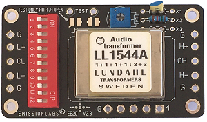
How to use this board?
This Lundahl transformers family is extremely versatile, due to the great number of windings. So despite the small size, there are many possibilities, all of which are set by the Piano switch, and by the way the board itself will be connected inside the amplifier.
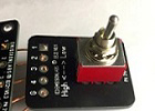
The external switch option is not necesary to use, but gives some extra comfort. It allows to change the input sensitivity of the amplifier. We supply a high quality switch, with internal silver contacts, but if you want to use your own, you could also do that. In that case, connect for instance a two position rotary switch, of your choice, to the external switch board EE22.
- This board can be used stand alone, or with the external switch. Both methods allow for all gain options. (See below)
- Choose the intended gain/attenuation factor from Col.2
- Then choose the transformer from Col.1.
- LL1550 vs LL1544 or LL1545. These have some overlap. Use LL1550 only for high transfer ratio applications. If the gain you want to achieve is as possible also with LL1544 or LL1545, these are preferred. The difference between LL1544 and LL1545 is the core material, so not the connection methods.
- Stand Alone: Use Piano Switch Options from Col.7
 With External Switch EE22 attached: Use Piano Switch Options from Col.8
The switch will move the gain up or down the selection one row. This is called "Low" and "High" in Col.8.
UNBALANCED to BALANCED (not moving coil)
Note the many gain variations, the EE20 board allows. LL1544A/LL1545A and LL1550 differ only on windings number. Mainly the LL1550 has less primary windings, giving 2x the step up ratio. Yet, 2x higher step up ratio of 1550 must be payed with 4x lower Input impedance. So LL1544A is probably the most recommended, because input impedance stays above 3k, and LL1544 can even attenuate if needed. Note, that attenuation reduces also noise of the driving signal. It can (and should) simply be tried what works best, by testing all gain settings.
Col. 1 |
Col. 2 |
Col. 3 |
Col. 4 |
Col. 5 |
Col. 6 |
Col. 7 |
Col. 8 |
Trans-former |
Board Gain |
Name |
Possible Use |
Input impedance if amplifier load is 47k |
Value of R1 to get 47k input impedance. Insert J1 and J2 for this. |
Stand Alone. Piano Switch Numbers |
With External Switch Option3 Low / High is the switch position |
0.5x |
New! Possible with EE20 board |
188k. |
15k |
1, 3, 7, 9, 11 | 7, 9, 11, Low (High = 2x more gain) |
||
0.75x |
New! Possible with EE20 board
|
84k |
47k |
1, 3, 5, 7, 8, 11 | 5, 7, 8, 11, Low (High = 2x more gain) |
||
1x |
Lundahl Alt A |
10k / 10k |
47k |
Remove R1, this. will give 47k. |
2, 7, 9, 11 | 7, 9, 11, High (Low = 2x less gain) |
|
1x |
Lundahl Alt B |
600R / 600R *3) |
n.a. |
Remove R1 |
1, 3, 5, 7, 8, 10, 12 | 5, 7, 8, 10, 12, Low (High = 2x more gain) |
|
1.5x |
New! Possible with EE20 board
|
21k |
*1) |
2, 5, 7, 8, 11 | 5, 7, 8, 11, High (Low = 2x less gain) |
||
2x |
Lundahl Alt C Most recommended |
High Signal |
12k |
*1) |
2, 5, 7, 8, 10, 12 | 5, 7, 8, 10, 12, High (Low = 2x less gain) |
|
2x |
Lundahl Alt D Only for low impedance Source |
Normal Signal |
12k |
*1) |
1, 3, 4, 5, 6, 8, 10, 12 |
4, 5, 6, 8, 10, 12, Low (High = 2x more gain) |
|
4x |
Lundahl Alt E |
3k |
*1) |
2, 4, 5, 6, 8, 10, 12 | 4, 5, 6, 8, 10, 12, High (Low = 2x less gain) |
||
1x |
New! Possible with EE20 board
|
47k |
Remove R1, this. will give 47k. |
1, 3, 7, 9, 11 | 7, 9, 11, Low (High = 2x more gain) |
||
1.5x |
New! Possible with EE20 board
|
20k |
*1) |
1, 3, 5, 7, 8, 11 | 5, 7, 8, 11, Low (High = 2x more gain) |
||
2x |
Lundahl Alt A |
High Signal |
12k |
*1) |
2, 7, 9, 11 | 7, 9, 11, High (Low = 2x less gain) |
|
2x |
Lundahl Alt B |
Normal Signal |
12k |
*1) |
1, 3, 5, 7, 8, 10, 12 | 5, 7, 8, 10, 12, Low (High = 2x more gain) |
|
3x |
New! Possible with EE20 board
|
5k2 |
*1) |
2, 5, 7, 8, 11 | 5, 7, 8, 11, High (Low = 2x less gain) |
||
4x |
Lundahl Alt C |
High Signal |
3k |
*1) |
2, 5, 7, 8, 10, 12 | 5, 7, 8, 10, 12, High (Low = 2x less gain) |
|
4x |
Lundahl Alt D |
Normal Signal |
3k |
*1) |
1, 3, 4, 5, 6, 8, 10, 12 |
4, 5, 6, 8, 10, 12, Low (High = 2x more gain) |
|
8x |
Lundahl Alt E |
734 Ohms |
*1) |
2, 4, 5, 6, 8, 10, 12 | 4, 5, 6, 8, 10, 12, High (Low = 2x less gain) |
||
*1) not possible to get 47k. Remove R1. *2) This 1:1 configuration transfers high impedance 1:1. So 10k in = 10k out, or 47k in = 47k out. Etc. *3) This 1:1 configuration transfers low impedance 1:1. So 600R in = 600R out, or 1k in = 1k out. Etc. |
|||||||
1. GAIN Applications
LL1544a is an amorphous core transformer, and can do anything from 0.5x gain until 4x gain in fine steps, with the EE20 board.
LL1545a is a mu-metal version of LL1544a.
LL1550 is an amorphous core transformer. It gives always gives gain, from 1x to 8x. So when the gain range of 1544a (0.5 ....4x) is not enough, LL1550 can be used. There is no mu-metal version of LL1550.
2. ATTENUATING Applications
This is a curious way to use the EE20 Board, but it is sure possible and a very good way. When the compensation section is switched off, by opening the Jumper J10, the board can be reversed. For the logic, the "High Signal" side has the H+ and H- inputs, and the "Low Signal " side is called L- and L+. For attenuating, the input is H+ and H- and the attenuation factor becomes what was originally the gain (just use the above table for Switch settings. So set the board for instance of 4x gain, and reverse it, to get 4x attenuation. So attenuation of the reversed EE20 Board can be varied from 0.5x (which is gain) to 4x attenuation using LL1544A, or get an attenuation from 0 to 8x with LL1550. Moreover, when attenuating, the frequency compensation will not be needed anyway, because we can assume a low impedance signal source.
Advantages of attenuating: Basically this situation is as follows: The power amplifier has more gain as needed. So the amplifier begins to distort much for before the volume is at 100% loudness. Now with an attenuating board, the input signal has to be higher, which signal level is of course available. With 99% of the signal sources, this will improve the signal to noise ratio in the same ratio as the attenuation itself! So an drastic noise reduction will take place! The
Using LL1544A / LL1545A reversed, give attenuation of 4x, 2x, 1.5x, 1x, 0.75x or 0.5x (The last two options are in fact "gain"). All if this by just set the piano switch by the table.
Using LL1550A reversed, gives attenuation of 8x. 4x, 3x, 2x, 1x.
3.1 Create a balanced RCA input.
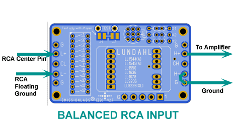 Most RCA connectors are grounded to the chassis by default. To convert this to a balanced RCA input, it should be replaced by an isolated ground type. Sometimes such an isolated ground RCA connector was already used, and it's ground was connected to the chassis with a wire piece. In that case, just cut this wire piece off. The center of the RCA cable is connected to X+. The shield is connected to X. Already now the input is balanced, even though it has RCA connectors.
3.2 Create a real XLR input
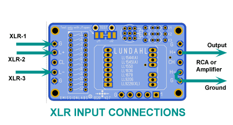 We don't want to mention names here, but some amplifiers have fake XLR inputs. Which are simply wired internally to an unbalanced input. So the amplifier already has all of the hardware, just the transformer was not installed. In this case, using the EE20 board is a VERY GOOD idea..
Note: You can even attach an RCA and XLR input TOGETHER, when connected like in the above pictures.
3.3 Create a Gain stage (unbalanced)
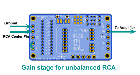
This is how to create a simple gain stage inside an amplifier. Select any ration from 0.5x (Attenuating) to 4x (Gain), by simply set the Piano switch by the table. This is using LL1544, LL1545, which are probably the most convenient to use, because these will also ATTENUATE if needed (So gain = 0.5x) if needed.
With LL1550, Gain can be selected from 1x to 8x. Whereas input impedance becomes quite low at 8x gain, impedance will be the same as with LL1544 or LL1545, if the same gain is chosen.
Moreover, by adding the Optional EE22 Switch Board in addition, the amplifier becomes a High-Low Sensitivity input.
3.4 Create an Attenuating stage (unbalanced)
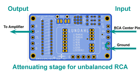
By reversing the direction of the board, all gain factors from the table will become attenuating factors. This is much recommended if you have too much signal. In such a case, the pre-amplifier noise may become too high, the volume control is working on too small rotation angle, and the pre-amplifier will sound sterile too. This attenuating mode, will reduce the noise by the same ratio as the setting of the table. So at 4x (from the table) noise attenuation will be 4x as well. Since this is hard to predict what is needed, this EE20 board is ideal, because it provides so many possibilities.
3.5 A balanced input with center tap.
When a balanced signal source is floating, there is some risk on common mode signals being picked up, when the balanced input is also floating. In this case, the center tap of the EE20 input can be grounded, by setting Switch A5 to 'on'.
3.6 Create an unbalanced input.
For this, either X can be grounded, or X+ can be grounded, depending if phase reversal is wanted or not. Ground Terminal X by setting Switch A6 to 'on'. Or, Ground Terminal X+ with Switch A4 to 'on', which results in phase reversal. From switches A4, A5, A6, use only one at a time!