Electron Engine ™
Printed Circuit Boards by Emissionlabs
 Introduction (You are here)
- Use of Triode Board (EE12) with Power Supply EE11
- Use of Triode Board (EE12) with external Tube Tester
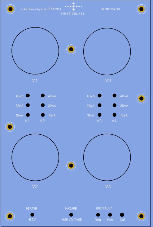
- Use of Pentode Board (EE14) with Power Supply EE11
- Tube Data Table
- Typical Test sequence
- About the purpose of burn in.
- Fusing of the boards.
- Building instructions
- Options and Support
Tube Test System EE12 Version3. Introduction.
Building this burn in system is really a nice project, and we took out time to document this in detail, and help you understand how and why burn in is done.
Though the boards and documentation looks complex, the functioning is not difficult. Also, the boards are generally very forgiving in case of a mistake.
Dimensions
- EE11 Power Supply Board: 61x 146 mm.
- EE11 height: Reserve appr 60mm for the ring core transformer
- EE12, EE14, EE15 Tube Boards: 127 x 193 mm. .
The Version V3 is similar to V2. Differences are:
- Heater voltage LEDs, Grid current and Anode LEDs are now on the socket boards, to reduce wiring.
- Additional fuse was added to the power supply board.
- PCB trace coils have been added for improved RF decoupling.
- The version V3 can work on AC and on DC voltage for the grid and anode.
An interesting hint, of what do with tubes, stored for a long time, is found in the Raytheon 5755 datasheet (from www.4tubes.com). They write on page 2, note 2, this message: 'Tube data is only correct after 150 hours of burn in, using a typical circuit for that'. So what is a typical circuit? Click here to read some information about the Raytheon test circuit.
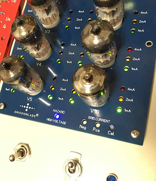
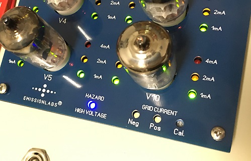
Test System EE12, pictured here is Version2. Version3 has the LEDs for 6.3V /12.6V integrated in the tube test PCB. For the rest the PCB is the same.
Please note, the final build needs a cover to make it safe.
This is a modular tube test and burn in system. We sell this product is a kit. We supply the bare PCBs and almost all parts. What is not included is: The housing, Wires, Mains outlet plug, mains switch, anode voltage switch, a knob for the grid voltage potentiometer, and mounting screws. All other parts are included.
- EE11. Power supply board with transformer, for the following boards
- EE12 Test Board, for 10 double Triodes like 12AX7, ECC88, etc.
- EE14 Test Board, for 4 pentodes like KT88, EL34, 6L6 etc. (under construction)
- EE16 Test Board, for 2 Octal rectifiers under maximum output power.(perhaps)
The main purpose is to burn in the tubes and do functional testing. Each board is capable to burn in the tubes, and while doing so, observe plate current, for all tube sections simultaneously, by means of LED indicators for the current.
The power supply can feed maximum 3x EE12 Boards, and 2x EE14 boards. All five boards have the power supply hooked up from the one board to the next. So wiring is simple. Only one type of tube can be tested at the same time. So you can not plug triodes in the EE12 boards, and pentodes in the EE14 boards at the same time.
Total anode power is maximum 100 Watts. This would be sufficient to burn in one octet of pentodes at 12.5 Watt each. If you want you can go to 25 Watt per pentode, for more powerfull testing, but this can only be done with four pentodes at a time.
With three EE12 boards, a maximum of 60 tube sections can be observed simultaneously, while burning in the tubes, and observe if and how they change.
Also more units can be combined in a master / Slave system. Schematic is here.
For burning in, we do not need to know tube curves, or precision data, to say what are good tubes, and what are bad tubes. Reason is simply, they have already been tested by the manufacturer, and all we need to do is, get them back to the condition they had at that time. This is the basic philosophy, which is explained over two pages, in the Blue Book, of the Max Funke, who spend his entire life building tube testers.
All we want to do, is bring the tubes to their intended condition. If a tube has a fault, that will be typically seen when it performs different from the others. Such a difference may go away during burn in, but if it gets worse, such a tube is a reject. Even when such a tube may tests 'good' on a normal tube tester, it is not like the others. It may become a trouble maker later.
Sometimes the whole lot goes down in performance, during burn in. Sadly, such tubes are around also, but it is better to know this anyway. Generally however, burn in will clean the tubes, activate the getter, reduce noise, and almost any kind of problem has a chance to go away. Like Raytheon says, give it 150 hours before you judge a tube. .
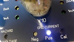 Grid current can be pre-tested and also monitored during burn in, for all tubes together on each board. Though grid shorts are rare, this can cause catastrophic trouble in the amplifier. Historical tube testers used a neon lamp for this, but I am sure they would have used LEDs if these would have been available at the time.
Some possible tubes to burn in:
5687, 5751, 5965, 6060, 6072, 6211, 6201, 6414, 6679, 6681, 6829, 6922, 7025, 7062, 7308, 7728, 8514, 6AQ8, 6CG7, 6DJ8, 6DT8, 6N1P, 6N2P, 6N6P, 6N11, 6N23P, 12AT7, 12AU7, 12AX7, 12AY7, 12BH7, 12DT8, A2900, CV455, ECC81, ECC82, ECC83, ECC85, ECC87, ECC88, ECC99, ECC186, ECC189, ECC801S, ECC802S, ECC803S, E81CC, E82CC, E83CC, E88CC, E182CC, M8162.
With some adapters sold on Ebay by the Chinese:
WIth 6SN7 to ECC82 adapter: 6H8C, 6H9C, 6SN7, 6SL7, 12SN7, 12SX7, 12SL7, ECC33, 5691, 5692, 6180.
With ECC808 to ECC83 adapter: ECC808