Electron Engine ™
Printed Circuit Boards by Emissionlabs
- Introduction
- Use of Triode Board (EE12) with Power Supply EE11
- Use of Triode Board (EE12) with external Tube Tester
- Use of Pentode Board (EE14) with Power Supply EE11
- Tube Data Table
- Typical Test sequence
- About the purpose of burn in.
- Fusing of the boards.
- Building instructions
 Options and Support (You are here)
Support
If you own an older version, please click here.
Options
These are just some ideas about things which would be possible.
- Using a Fan
In case the housing has not enough ventilation, connect a 230V or 115V AC fan (depending on your mains voltage) to the M1 and M2 inputs of the power supply board. - Run the tubes on DC voltage
AC voltage is harder for the tubes, because it pulses the current. This is in accordance with historic methods, where the tube itself is used as the rectifier as well.
DC voltage is more gentle and safer, bit it takes longer. It was recommended in the Raytheon data sheet. This option is under your own responsibility, but it was tested, and seems to work good. Please ask if you have questions, or ideas about it.
We supply the kit as AC version, but it is very easy to make it work on DC.
For DC testing, the following parts need to be added to the power supply board:
R1. 68k, 2Watt
C1 150uF, 350V
R6 15k. 1/4 Watt
C2 100uF, 100V
If you want to change back from DC to AC testing, the resistors R1 and R6 can be left in.
Using an internal mA meter for grid current.
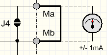 The grid current of each separate Socket Board EE12 is monitored with two white LEDs build in. These burn only if the threshold of +1mA or -1mA for the total board is exceeded. So this is not a current indicator as such, but only "grid fault" indicator. (so a short or leakage above 1mA). In case you are interested in measuring real grid current, starting at zero, connections for an analog mA meter are prepared on the power supply board. They are called "Ma" and "Mb". By default this link is closed with jumper J4, or just by a wire link between MA and MB. So when using an ampere meter, remove the wire link or open J4. Current range of the meter should be appr 0.1 ...1mA, and it should be a version for positive and negative current. Use only an analog meter, and it must be installed inside the tube tester housing. So there will be no risk on RF oscillation due to long wiring, or strange effects due to digital meters which have unknown electronics build in, which may introduce complications.
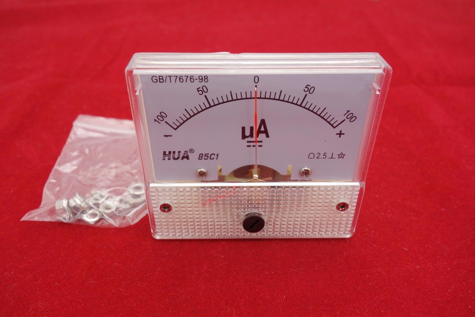
Such a meter like this is needed, or search for this Item number in Ebay:172934983437. Though Ebay part numbers will change quickly.
Heating with external AC or DC power supply.
In case you want to use a AC or DC voltage, for instance a DC module, it must be a FLOATING power supply.
Do NOT use a power supply which has one end grounded.
The external power supply should be 12.6 Volts, AC or DC. It will be used for for 6.3V and 12.6.V tubes, because the EE12 board connects two 6.3V tubes in series in groups of two, and 12.6V tubes are all in parallel. This method makes the power supply for 6.3V tubes run at only half the current, which makes the construction more convenient. So the 12.6V, 5.4A transformer we supply, can feed a total of 10.8A into 6.3V tubes.
H+ is the positive input, H- negative. AC or DC can be connected to it. For DC, f you wire it reversed by mistake, there will be no damage, but the tube heater LEDs for 6.3V and 12.6V will not work right. An external The DC module is best to build into the tube tester housing and shielded. This is to prevent RF oscillation, which may be caused otherwise by external cables, acting as antennas.
Heater current higher as the EE11 Power supply intends.
This is possible, but it is on your own responsibility. You are in uncharted waters, and you need to look carefully what you are doing. Switches, fusing and cabling needs to be adapted accordingly. Be careful, because a short with a high energy power supply can cause burn damage within just seconds. The EE12 tube boards are not the weak spot. These should be capable of quite some higher current, because their heater PCB tracks supply only 5 tubes together, and even these tracks are wide, and on both sides of the PCB. Just on the EE11 power supply it comes together for all 30 tubes, and it becomes a lot of current. You need to judge yourself how far you want to go with that, and what it takes. On the other hand, high current tracks of the heater part, on the EE11 power supply board, are only three very short pieces, and it is very easy to see where they are, and enforce them.
Notes for users of older versions
If you have an older version, there is full support, we still have it online, but not linked here. We have the documentation online, please inquire for a link. (Your old bookmarks still work)
The Version V3 is very similar to V2. Differences are:
- All LEDs are now mounted on the EE12 PCB, to make building easier.
- Additional fuse was added to the power supply board.
- PCB transformer coils have been added for improved RF decoupling.
- The version V3 works can work on AC and on DC voltage, as well for the grid and anode.