Electron Engine ™
Printed Circuit Boards by Emissionlabs
- Introduction
- Use of Triode Board (EE12) with Power Supply EE11
 Use of EE12 with external Tube Tester L3-3, or other. (you are here)
- Use of Pentode Board (EE14) with Power Supply EE11
- Tube Data Table
- Typical Test sequence
- About the purpose of burn in.
- Fusing of the boards.
- Building instructions
- Options and Support
Use of EE12 board with EXTERNAL tube tester L3-3, Roetest, or other.
Only for: VERSION V3 or higher.
Description
If you have your own tube tester, it is possible to connect the EE12 board to it.
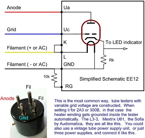
The Socket Board EE12 uses mixed bias. This is the professional method for burn-in and testing, like used in tube factories ever since. Mixed bias uses an auto bias resistor, but the grid is provided with a variable voltage as well. This voltage is made negative to cut off the tube, or it is made positive to increase the Anode current. It should not be set higher than the voltage at the auto bias resistor, otherwise grid current will occur. (The white LEDs will burn, you will see that) For the rest, during use, you can not see it is mixed bias. The board responds just to grid voltage change, with a change of the Anode current. Only this method is a lot safer, because it prevents thermal runaway of the tube.
Since mixed bias works with positive or negative control voltage, but the tube tester can only supply negative voltage, we need to use 50V higher anode voltage. So begin with 250V, but if there is not enough Anode current possible, even when the grid voltage coming from the tester, set at 0V, just increase the anode voltage some 50V.
What testers can it be used with?
The tester needs to be a parametric tester. Like the ones that can adjust the grid voltage and anode voltage, and measure the Anode current. Such testers are, all Roetest, AVO Mk1..4, VCM63, Metrix U61, and of course the famous KALIBR L3-3.
The tester is set for 300B and the 4-Pin socket for this tube is used. The EE12 is connected to this socket, using the base of an old tube, and just a four lead cable. Then anode voltage, grid voltage and heater voltage is set to the tubes you are burning in. Just the tester should be able to supply 20x the current of each system. Like when using 20x 5mA, it needs to supply 100mA.
Alternatively, also three power stand alone supplies can be used.
The right way to test tubes
Only trust vintage tubes data sheets. There can written in there:
- The test circuit.
- Minimum and/or maximum values
- average values
- Or...Nothing. (lots of empty boxes, like with JJ tubes)
The published method for professional tube testing, was ALWAYS auto bias or mixed bias. Amateurs are often testing with fixed grid voltage, not knowing this gives false results for transconductance.
Tube like C3m, C3g, but also the more known E88CC, ECC801S, ECC802S, ECC803S, have to be tested in mixed bias. The test circuits for this, are printed for instance here, in the Telefunken E88CC data sheet. Strangely, "Specialists" still test those tubes with fixed grid voltage, and do not understand why this is wrong.
In some USA data sheets (Raytheon or Tung-Sol), they say tubes have to be tested auto bias, and values are only valid after burn in. In other words, what you measure before burn in, is not relevant.
Telefunken says, you have to use this circuit for E88CC, and it is a MIXED BIAS circuit. I just drew it from the information they have in the text.
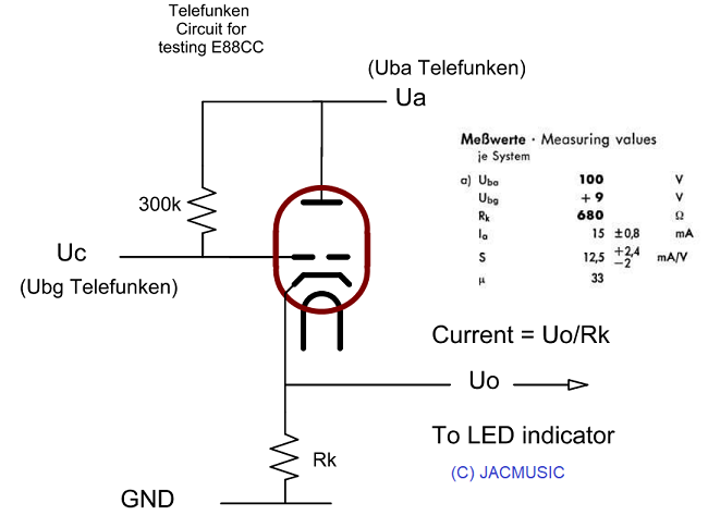 This means, the cathode is connected auto bias, but the grid voltage is variable. This is mixed bias. It allows to change the auto bias set point up or down, by supplying a positive or negative control voltage. Though the EE11 power supply can supply positive and negative control voltage, most tube testers can only supply only a negative grid voltage, which we are using here for the EE12 board, as control voltage. This means, when you see for instance -3V grid voltage on the tube tester, the tubes itself run NOT at -3V Grid voltage, but the cathode to ground voltage adds up to this. So the applied voltage to the EE12 board becomes only a control voltage, which number by itself is unimportant, because all we want to see, is the Anode current resulting from this.
And yes, EE12 is doing it that way. The only thing we can not do, is use that particular Cathode resistor value of the data sheet. But since we are only doing a burn in, and not verify the tube to the data sheet, that would still be a good way.
This ends the description part. Now comes how to build it
Using EE12, and prior to using it.
- First fit EE12 unit into a safe housing.
- Be aware, not to exceed the tube tester anode current or heater current. Tubes tubes like 5687 draw a lot of heater current. You just need to calculate it. The total Anode current draw is easy, you can just read that from the tester itself. There is no need to go to high Anode current. Even so, at lower Anode current burn in works out better.
- Set up the tester for anode voltage of maximum 275V, Grid from 0 to -30V. The heater voltage is taken from the tube data table. For owners of the Russian L3-3, we supply a dedicated 6V and a 12V test card, as pdf file by email
- When using EE12 for the first time, testing the tubes initially with a normal tube tester is a good idea. So you do not run into unexpected situations. The EE12 board will detect faulty tubes also, but you need some experience with that. A gassy tube will light up the white LEDs, or will not behave like the others, and will catch your attention quickly, when changing the grid voltage from cut-off to normal. At severe overload, most of the time the thermo fuses will respond, or otherwise the melt fuse at the PCB bottem. Read here about the fusing.
- Set the anode voltage to minimum, and the grid voltage to the most negative value the tester can do.
- Check heater voltage with the EE12 board and the tubes glowing.
- Slowly increase the anode voltage to the desired voltage, but do not go higher than 275V. If from a whole series of tubes, just one or two LEDS light up now, you need to stop, and remove these tubes, which are probably faulty.
- When desired anode voltage is achieved, all LEDS are off. Now adjust the grid voltage, making it less negative, and have the LEDs burn as needed. Small differences are normal, but basically all tubes should respond the same. If one tube responds much different to changes of Ug, this probably indicates a defect.
- If the white (grid current) LEDs are burning, remove the tubes one by one, to find the trouble maker. Also the external tube tester, should indicate this grid current. The grid current circuit of EE12 has a threshold, which is calibrated. So when the LEDs burn, this tube is definitely defective.
- A low current burn in, has better results as a high current burn in.
Construct a connection cable for your own tube tester, to the EE12 board
- At the EE12 Board, connect K to L. Supply the Positive end of the heater voltage to L. If the heater voltage of the tester is AC, it can be connected either way.
- Connect Ua of EE12 to the Anode voltage of the tester.
- Connect Uc of EE12 to the Grid voltage of the tester.
- Connect GND of EE12 to Electrical circuit ground of the tester.
- RG is connected with a 10k resistor to GND. This will make the red (12.6V) LED burn if the heater voltage is "on", regardless if the voltage is or AC or DC.
- If the red Heater LED is not burning with a DC heated tester, reverse the filament connections of the connection cable. With AC this doesn't matter, and the LED burns always. Only thing to be aware of, the red LED has '12V' written on it, but when using an external power supply, of course this is not 12V, but any voltage the external power supply delivers. By changing the 10k resistor, the brightness of the LED can be changed. The value must be above 2k2.