Using Power Supply Chokes
Introduction
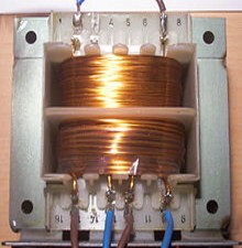
 All Lundahl products are based on their double coil (symmetrical) C-Core technology, using Audio Grade, self-made cores by the Lundahl factory directly. So indeed they produce the cores from magnetic foil themself. Also the chokes, and even the mains transformers. This means all power supply chokes are also possible to use as tube anode chokes. So unlike a regular chokes, the Lundahl chokes work up to 20kHz or more. A low cost choke is a terrible source of magnetic and electric field radiation for several reasons. The Lundhal chokes by definition are radiating almost nothing. First, because they are well over dimensioned, so you operate then nowhere near saturation, also not at maximum specified current. Second, the symmetrical construction with the double coil radiates a field for each coil which is in anti phase. So the net radiation field is very low. This double coil construction means you have always two coils available, in space oriented in anti-phase with each other, but connected electrically in phase of course. They are positioned each on the other side of the core, physically rotated 180 degrees. You cannot use the coils independent from each other, because that would make it a transformer. So you need to make sure on each coil is the same signal, and then it works.
If you feel too confused now... Read this another time. What applies for the mains transformer in this article, applies in fact for the chokes as well.
In short, simply put the two coils in series or in parallel, but make sure you wire them in phase. So use the connection scheme of the datasheet. You can wire them in three ways:
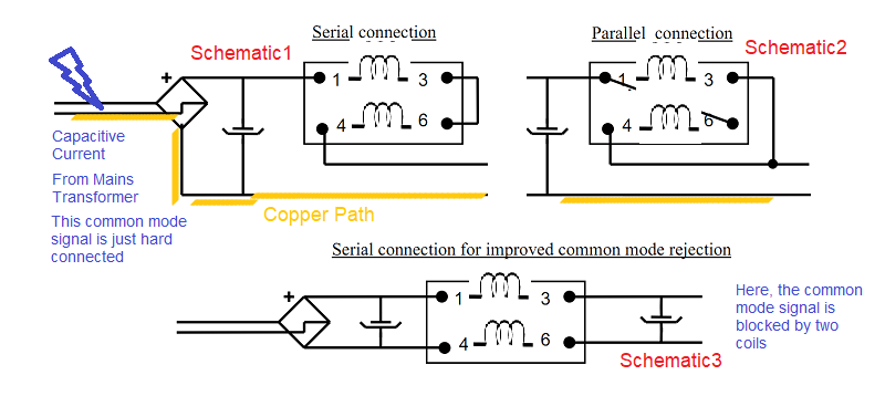
- in Series. This is how the Henry value is specified. If you buy a 10H choke, it will have 10H with both series.
- in Parallel . This option has only 50% of the inductance, but for that you have twice the current and half the DC resistance. The best thing to do is, check the price list of jacmusic.com because in there is a compact overview of what is the best coil for a required DC current. Most if the time series connection gives the best value for money, but with some
- in Common Mode Rejection configuration. Schematics will follow in the text, down here. In this configuration, one coil is in the positive lead to the second capacitor, and one on the ground lead to the second capacitor. This will give lowest field radiation coming from the choke. Such good results cannot be achieved with lower cost E-Core chokes, and the Lundahl double coil chokes are a major step into the direction of a really hum-free amplifier. Electrically this is calculated as a series connection. More information also here below.
How to Select the right Choke.
Data sheets can be confusing sometimes. You normally will know the required DC output current. Choose this in the table. Then on the right, you see some choices for induction. If there are multiple options for the induction, that is because some transformers have low DC resistance, others have high DC resistance. A low DC resistance chokes will be less warm, but usually offers less inductance. A higher DC resistance offers extra filtering, and protects better against surge current when the capacitors are empty at switch on. Such effects must be well considered. So a low DC resistance is not always better, but it may be useful when you have heat problems, or other power supply limitations So each coil has it's own advantages, but the higher resistance coils should be taken when you have the possibility. Moreover, the higher Copper Resistance is an additional filter element. So yes, you need to produce 21 or 2 Watt more energy, but charge slopes for the capacitors are not so aggressive, and the extra filtering means, you could save a little bit on the size of the capacitors, and have the same effect still.
When looking in the table, sometimes you may find a type, with just a little more current, and you will have a much large inductance. Though often this is a type with a larger core, or thinner wire, so to get more windings on the core. So by looking in this table, you find what you need must faster than by looking in the datasheets. This saves you a lot of time. In this table are listed only the useful combinations. Many parallel configurations are not interesting. The few that are, you will find listed, but we aware these have no CMR possibility, which is just what makes the Lundahl so nice.
Furthermore, "useless" configurations are not listed in this table, like connect both coils of LL1667-20mA in parallel, this would give you a 40mA coil, but at 50H only. Which is not as good as LL2743-70mA which has even 64H. Even so, LL1667-20mA in parallel has only 195V maximum AC over the coil, which is quite a limitation. All in all LL2743-70m would be a better coil in that case, and LL1667-20mA connected for 40mA is not even listed here. So below here, are only good and useful combinations.
LL2742 is interesting, as it has double weight, it has huge core of 2.5kg. This gives outstanding performance, and yet price is almost the same as the standard core types of 1.35kg.
LL1685 is a small core type, yet the inductance was made possible by using thinner wire, this results in relatively high inductance still, at the cost of higher copper loss, but not even that much higher. (The trick is, the smaller core has also smaller diameter). Also maximum RMS Ripple voltage is a fraction smaller. All in all, these perform amazingly nice, and of course have only half the size, and are a fraction lower price. A good seller.
Amorphous cores are a specialty for itself, this is no normal steel, but a alloy of glass and metal, having no crystals and much nicer hysteresis curve. Note, they have the same inductance as the "mother" type, but only HALF the maximum AC voltage over the coil. Typically that would be no problem in a C-L-C filter, but they cannot be used in an "L-C" filter. We are probably able to get ANY Choke for you in Amorphous version, on customer order.
Is it possible to exceed the maximum plate current?For application as anode choke the answer is in often YES! , but for application as power supply choke, the answer is normally NO!
![]() For application as a power supply choke, theoretically you could exceed the plate current, when you have a C-L-C circuit, and for that reason not much AC voltage across the choke. However, at switch on, the capacitors are empty, so voltage across them is zero. However, the transformer gives full voltage, and the rectifiers and chokes will have to digest this full voltage, which they are not y made for. So during that one second, the choke may be subject to very high voltage. Combined with the charge current of the capacitor, this would saturate the choke, and it becomes a copper resistance at that moment, damaging the rectifier, now or later. So if the choke saturates, DC current will sharply rise, and not go away before the capacitors are full, and saturation disappears. We only write this here, to spark some thoughts about this.
For application as a power supply choke, theoretically you could exceed the plate current, when you have a C-L-C circuit, and for that reason not much AC voltage across the choke. However, at switch on, the capacitors are empty, so voltage across them is zero. However, the transformer gives full voltage, and the rectifiers and chokes will have to digest this full voltage, which they are not y made for. So during that one second, the choke may be subject to very high voltage. Combined with the charge current of the capacitor, this would saturate the choke, and it becomes a copper resistance at that moment, damaging the rectifier, now or later. So if the choke saturates, DC current will sharply rise, and not go away before the capacitors are full, and saturation disappears. We only write this here, to spark some thoughts about this.
Please CLICK HERE to read more about it, but this applies for use a anode choke
Some comments for this table:
-
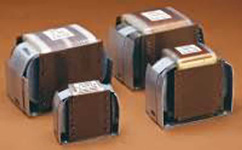
There are two core sizes. Large (1.35kg), and small (0.75kg). The smaller chokes are lower cost and lower weight. For that, they will have less current and less inductance. However, when inductance or DC current suits you, these are a good choice. .
-
Chokes can optimized for highest inductance, at the cost of more DC resistance. This is good because there is less risk of saturation at switch on, specially at high inductance. Such are LL2743.
-
Chokes can be in middle, so current is medium, with medium resistance and reasonable inductance. Chokes can be optimized for high current. By nature, the user will require low DC resistance in such a case. These have medium inductance.
-
All chokes can be used as high current choke, by paralleling the two coils. These have low inductance. Theoretically this is possible with all chokes, but not always the result is a choke better than already existing chokes. In case where this makes sense, we list them here too. For very high current applications this is the normal way.
Connect internally: |
CMR Config? |
R-DC |
Voltage Loss Max |
power Loss Max |
Max RMS
|
First Sorted
|
Then sorted
|
Weight
|
Special remarks about specific use |
|
Series
|
Yes |
2400Ω
|
12V
|
0,06W
|
390V~
|
5mA
|
810H
|
1,35
|
Normal Choke | |
| LL1667-07mA | Series
|
Yes |
2400Ω
|
17V
|
0,1W
|
390V~
|
7mA
|
580H
|
1,35
|
Normal Choke |
| LL1667-10mA | Series
|
Yes |
2400Ω
|
24V
|
0,2W
|
390V~
|
10mA
|
405H
|
1,35
|
Normal Choke |
| LL1667-15mA | Series
|
Yes |
2400Ω
|
36V
|
0,5W
|
390V~
|
15mA
|
270H
|
1,35
|
Normal Choke |
| LL1667-25mA | Series
|
Yes |
2400Ω
|
60V
|
1,5W
|
390V~
|
25mA
|
168H
|
1,35
|
Normal Choke |
| LL1668 5-7-10mA |
LL1668 is an anode choke, and has npo use as power supply choke. LL1667 has more inductance, and voltage drop of LL1667 is low enough. |
|||||||||
| LL1668-15mA | Series
|
Yes |
680Ω |
10V
|
0,2W
|
235V~ |
25mA
|
167H
|
1,35
|
Low DC Loss, but less inductance |
| LL1668-25mA | Series
|
Yes |
680Ω |
17V
|
0,4W
|
235V~ |
25mA
|
100H
|
1,35
|
Low DC Loss, but less inductance |
| LL2743-70mA | Series
|
Yes |
400Ω
|
28V
|
2,0W
|
450V~
|
70mA
|
64H
|
1,35
|
High Inductance, but more DC loss. |
Series
|
Yes |
130Ω
|
11,7V
|
1,05W
|
330V~
|
90mA
|
19H
|
0,75
|
Small Size, but more DC loss and less Inductance. | |
| LL2743-90mA | Series
|
Yes |
400Ω
|
36V
|
3,2W
|
450V~
|
90mA
|
50H
|
1,35
|
High Inductance, but more DC loss. |
| LL1673-20H | Series
|
Yes |
60Ω
|
6V
|
0.6W
|
400V~
|
100mA
|
20H
|
1,35
|
Normal Choke |
| LL1673-20H-AM | Series
|
Yes |
60Ω
|
6V
|
0.6W
|
200V~
|
100mA
|
20H
|
1,2
|
Amorphous, but only half max AC possible. Note the transformer has lower weight, as the core has 50% glass content. |
| LL1685-17H | Series
|
Yes |
130Ω
|
13V
|
1,3W
|
330V~
|
100mA
|
17H
|
0,75
|
Small Size, but more DC loss and less Inductance. |
| LL1685-17H-AM | Series
|
Yes |
130Ω
|
13V
|
1,3W
|
165V~
|
100mA
|
17H
|
0,65
|
Amorphous, but only half max AC possible. Note the transformer has lower weight, as the core has 50% glass content. |
| LL2743-110mA | Series
|
Yes |
400Ω
|
44V
|
4,8W
|
450V~
|
110mA
|
41H
|
1,35
|
High Inductance, but more DC loss. |
| LL1685-13H | Series
|
Yes |
130Ω
|
16,9V
|
2,2W
|
330V~
|
130mA
|
13H
|
0,75
|
Small Size, but more DC loss and less Inductance. |
| LL1685-13H-AM | Series
|
Yes |
130Ω
|
16,9V
|
2,2W
|
165V~
|
130mA
|
13H
|
0,65
|
Amorphous, but only half max AC possible. Note the transformer has lower weight, as the core has 50% glass content. |
| LL1673-15H | Series
|
Yes |
60Ω
|
8,4V
|
1,2W
|
400V~
|
140mA
|
15H
|
1,35
|
Normal Choke |
| LL1638-10H | Series
|
Yes |
36Ω
|
5,8V
|
0,9W
|
300V~
|
160mA
|
10H
|
1,35
|
Normal Choke |
LL1685-90mA |
Parallel
|
No. CMR is only possible if in Series |
32,5Ω
|
11,7V
|
1,05W
|
115V~
|
180mA
|
4.8H
|
0,75
|
Small Size, but more DC loss and less Inductance. |
| LL1673-10H | Series
|
Yes |
60Ω
|
12V
|
2,4W
|
400V~
|
200mA
|
10H
|
1,35
|
Normal Choke |
| LL1673-10H | Series
|
Yes |
60Ω
|
12V
|
2,4W
|
400V~
|
200mA
|
10H
|
1,35
|
Normal Choke |
| LL1638-08H | Series
|
Yes |
36Ω
|
7,2W
|
1.4W
|
300V~
|
200mA
|
8H
|
1,35
|
Normal Choke |
| LL2742-250mA | Series
|
Yes |
160Ω
|
20V
|
10W |
640V~
|
250mA
|
17H
|
2,5
|
This chokes offers very high conductance, but it is at the cost of higher heat development, 10 Watt at 250mA in Series. The coil will get quite hot, but it is made for it. |
| LL1673-08H | Series
|
Yes |
60Ω
|
15V
|
3,8W
|
400V~
|
250mA
|
8H
|
1,35
|
Normal Choke |
|
OBSOLETE TYPE. |
Series
|
Yes |
36Ω
|
7,2V
|
2,0W
|
300V~
|
280mA
|
5,3H
|
1,35
|
Normal Choke |
| LL1685-10H | Parallel
|
No. CMR is only possible if in Series |
33Ω
|
10V
|
3,4W
|
165V~
|
320mA
|
2,5H
|
0,75
|
Small Size, but more DC loss and less max AC |
| LL1638-04H | Series
|
Yes
|
36Ω
|
14,4V
|
5,8W
|
300V~
|
400mA
|
4H
|
1,35
|
High Inductance, but more DC loss. |
| LL2742-250mA (will do 500mA in parallel) |
Parallel
|
No. CMR is only possible if in Series
|
40Ω
|
20V
|
10W |
320V~
|
500mA
|
4H
|
2,5
|
This chokes offers very high conductance, but it is at the cost of higher heat development, 10 Watt at 500mA in Parallel. The coil will get quite hot, but it is made for it. |
LL1673-08H |
Parallel
|
No. CMR is only possible if in Series
|
15Ω
|
7,5V
|
3,8W
|
200V~
|
500mA
|
2H |
1,35
|
Fine choke, when you can work with 200V~, and no CMR configuration possible |
| LL1638-5.3H (will do 560mA in parallel) |
Parallel
|
No. CMR is only possible if in Series
|
9Ω
|
5V
|
2,8W
|
150V~
|
560mA
|
1,3H
|
1,35
|
Normal Choke |
| LL1638-04H (will do 800mA in parallel) |
Parallel
|
No. CMR is only possible if in Series
|
9Ω
|
7,2V
|
5,8W
|
150V~
|
800mA
|
1H
|
1,35
|
Very High Current, but more DC Loss |
In the double coil configuration (CMR CONFIGURATION), one coil is in the current supply path, and the other in the current return path. Electrically they will behave like in series. With all magnetic devices, there is some unwanted magnetic and electric field. Both can radiate into pre amplifier stages, or driver stages. Causing very difficult to understand hum. Lundahl uses a magnificent way, to reduce both the magnetic and electric stray fields to lowest possible level, you may not believe until you have experienced it. For this, all Lundahl transformers have always TWO completely identical coils on the core. This will produce the stray fields each in opposite orientation. At some distance, these fields will phase out each other. Such a result cannot be achieved with a lower cost E-Core choke, as windings have the same orientation. Even so, with ring cores, only the magnetic field will phase out over a distance, but not the electric field, as all windings have the same electrical field orientation. So for me, the Lundahl double coil chokes are the best step into the direction of a really hum-free amplifier.
The datasheets gives a good diagram of how to connect a double coil choke, using this feature and get best noise rejection from it. (check for instance here, all at the bottom of the last page). Yet if you want so, it stays always possible to use them as a single coil. That will be the case when you put the coils in series directly on the transformer, and wire it like one single choke. So the choice is always yours.
Overview of types
| 1 ) LL1638-Series | Wound with thick wire. Gives best performance for High Current applications. Available with different air gaps, which results in different current / henry. |
| 2) LL1673-Series | Same as above, but wound with medium thin wire. Gives best performance for High Henry applications. |
| 3) LL1685-Series | Same as 1673, but wound on the next smaller core. Lower in price, but less Henry. |
| 4) LL2742-Series | Higher inductance series, but wound with thin wire, with higher resistance . Technical limit: 250mA in series gives 10 Watt dissipation in the coil. |
| 5) LL2742-Series | Higher inductance series, but wound with thinnest wire. Resistance is 400 Ohms in series. Technical limit: 158mA in series gives 10 Watt dissipation in the coil. |
| Note: | In the above table, only the best and useful combinations are given. |
SOME DESIGN RULES FOR A HUM-FREE TUBE RECTIFIER CIRCUIT
Standard circuit diagram, with well defined earth point.
In this circuit diagram the primary Capacitor is C1, the secondary Capacitor is C2.
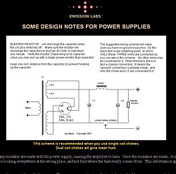
Old circuit diagram. Power supply of Kaneda Pre-Amp. The Lundahl equivalent is the previous schematic (above).
The strange way to draw the transformer has probably to do with how it was wound. Indicating here it was one core, with two windings on it. As the lower winding has reverse current, it must be connected reverse. That is something similar as Lundahl is doing. It is the first time I saw this technology elsewhere. The Lundahl is a much further development, as it is not two windings on one core. The Lundahl has two physically separated coils with opposite physical direction, which are then coupled magnetically. Like this, magnetic fields are identical and in phase, but stray fields in air are in anti-phase. In that way reducing radiation drastically.
Emission Labs Application Note about improved CMR Coil connection - CLICK HERE
With High Voltage power supplies, the best results are always coming from a large choke. This has many times more effect than using large capacitors.
- The BIG misunderstanding from people that made low voltage power supplies before. Here, using BIG capacitors, like 10.000...50.000uF will improve the result, because with Low Voltage designs, the energy storage is only in the primary capacitor. Not so with tube rectifiers! These are high impedance, and the energy storage is mainly in the choke. With tube rectification, you need to take the a small primary capacitor. (see also the next note). There is a maximum value for that in the tube datasheet. It is for instance 4uF for the 274A. The maximum is the highest value, and you should feel free to take a lower value also. The higher the value, the larger the charge current through the primary capacitor. The wires will radiate an AC magnetic field, and this gives hum into the pre-amp. (and you'll never find where this hum is coming from. The path is through air....)
- Some applications leave the primary capacitor completely away, and use only the energy storage in the choke. This will improve the efficiency of the power supply, and gives more current. This is a method, not recommended with low cost chokes, because it will make the plate choke hum (mechanically). With the LUNDAHL chokes this is possible, and no hum will result from it.
- Push pull amplifiers are very insensitive to power supply hum. They can work completely without hum, even with 30Volt AC on the DC voltage, but.... only as long as the rest of the construction is well done.
- SE amplifiers are very sensitive, but if there are any hum problems it is normally not the power supply. Improving the power supply first capacitors can will help, because it reduces all AC voltages in the whole amplifier. Still you are curing the problem at the wrong place, and never get a full cure because of that. More often it is bad wiring, or some other mistakes somewhere. The recommended capacitor values in the circuit diagrams are normally more than enough.
- With Mercury rectifiers people often say they "hum", or sound in some way "unquiet". That is true, but it comes from bad designs. Good designs do not hum at all. These rectifiers have an "ignition" before they get in the conductive state. Because of that, they have a lower internal impedance, and can work with surprisingly large primary capacitors. But... this is the industry method, and not what we want for HiFi. Again.... what these rectifiers show in their datasheets are maximum capacitor values for industry applications, and no "must use" values for HiFi! Take the same low primary capacitor value as for non-mercury rectifiers, and you will have no hum.
Here is the final conclusion:
If you want to oversize the power supply, the best effect comes from:
a) The CHOKE
b) The SECONDARY Capacitor
c) there is no c;)