Universal board EE08
Are these PCB difficult to use?
No! They are intended to make things work out better!
Sometimes, a user needs to try out a few things first, by soldering loose wires on the pins. This has some risk with the PCB transformers. When the wire is too thick, you would rotate the pin, when bending the wire. If this happens, it breaks off the internal wire, and the transformer is damaged.
If a set up doesn't work, many suspect a defective transformer, and people test all windings with a multi meter. However the multi meter injects 1mA into the winding, and an amorphous core becomes permanently magnetized. Please trust, the transformers are already tested by Lundahl, and a non working circuit rather means practically always, a wring error was made.
A challenge with fault finding is, any error occurs always at all windings at the same time. That is because all windings are transformer coupled. The Design Notes cover some of this, but using the EE08 board, prevents wiring mistakes from the beginning.
Moreover the transformer pins are not intended for repeated soldering. This will loosen the pins, and the internal wiring can break off. All of this is solved by the EE08 board.

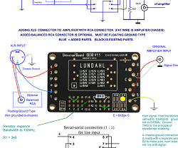
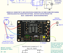
Click here for full size schematic
The EE08 board can do two things:
- Use it as a break out board. This is when you want to hard wire the transformer externally. Mostly for experiments with lots of cables attached. When it works, you can either leave it as is. Or, remove everything, and rewire it as complete board, which results then in shorter and cleaner wiring. More about the Break Out board application.
- Use it as a complete board, with the Lundahl data sheet applications. We have added all of these (and a few more) in the configuration examples in the table below. This is in how such a transformer could be used. This uses the small matrix field at the PCB bottom to make the windings connections. More about complete board application.
Features of EE08 PCB
- Length x Width: 70mm x 46mm
Mounting Hole distance: 62.2 x 38.1mm (hole center)
Mounting Hole diameter: 3.5mm - Gold plated with ground plane at each side. The ground plane is not directly visible, because the black solder mask is over it, but it is gold plated as well.
- The ground plane also closes the opening the transformer has, at the bottom.

 Much better behavior compared too loose wires. A 150kHz sine wave is passed without any loss, and also a 1kHz Square wave without any overshoot at all, with LL1570 (See below).
 - Core + Can are connected, if such a connection exists on the transformer itself.
- Transformer's static shield is connected, if such a connection exists on the transformer itself.
1. Use EE08 as Break Out Board.
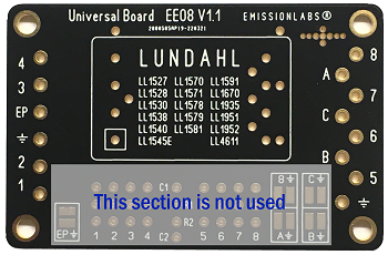
The matrix section is not used, and the side connections of the PCB, correspond with the data sheet pin numbers. Just connect this to your own circuit, the way you want it.
2. Use EE08 as Input/Output Board
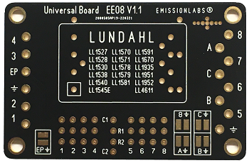
- This PCB replicates the many data sheet applications of Lundahl. See below table for connections. Or, implement your own application, by making the connections on the wiring field, they way you want it yourself. (Circuit Diagram is here)
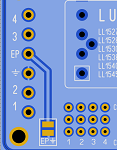
- All grounding schemes are possible, with Solder Bridges: EP, 8, A, B or C.
- There is room for termination components C1, C2, R1, R2. Initially it works also without.
- Effectively, EVERYTHING as in all data sheets can be realized with this PCB.
For testing, do not use an Ohms meter. This will magnetize the core. For measurements, do so with AC signal only. Also read under "Notes".
Mounting the transformer. Some transformers will fit in the board only in one position. For transformers, which also can be mounted rotated, these must be inserted with it's text oriented the same way as on the PCB.
 Double check this: At the board, Terminal1 is marked with a square. Double check in the data sheet, where is Terminal1.
Primary Load: If the application requires it, a resistive load it can be added across the primary, use the lower row for this, and solder the resistor on the corresponding Pins. Example: When a load of 1k is required from Terminal1 to Terminal3, insert the resistor in the holes 1 and 3. Each of the vertical rows are connected to each other. So it doesn't matter which "1" or "3" you take.
Secondary Load: For higher impedance transformers, it is often useful to add a small RC networks across the secondary. These transformers work without such a network as well, so don't bother about this from the beginning. Add the network as final touch, it will improve the frequency range and reduce phase error.
Example: If by the data sheet, an RC network is needed between Terminal7 and Terminal8, connect the Resistor with one end to 7 and the other end to R1. Connect the Capacitor with one end to 8, and the other end to C1. In the case of two RC networks, like with a splitter, the second pair is connected to R2 and C2. It is that easy! Example is here.
Ground. WIth some special transformers, Pin8 must be grounded. You will see this in the data sheet of the transformer itself. If so, add a solder drop on Bridge "8".
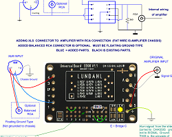
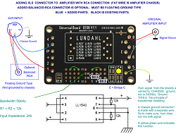
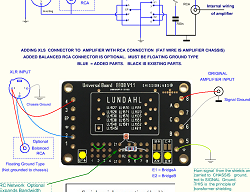
In the Lundahl data sheets, you will see a primary ground EP with some transformers. Sometimes it is needed to connect this externally to circuit ground. In that case, use the solder bridge EP for this. All grounding schemes are already in the data sheets. Just do it as it writes there. Some transformers have internal shields, called EP, E, E1 and E2. Unfortunately, Lundahl did not use uniform numbering for the secondary shields, but a short look at each of the data sheets, will show you the right lettering. To have it not confused from our side, we called the secondary shields. A, B, C, and we do not use the letters E, E1, E2 on the PCB.
Asymmetric Output (One signal wire only, which signal is vs. ground)
Though this is not specifically mentioned in most data sheets, it is a possible application for all transformers. For this, (only) Pin 8 can be grounded. It this case, it becomes a none data sheet application, but such can be many. Begin with grounding Terminal8, by adding a solder drop on bridge J8. Then, from there decide if the secondaries are in parallel or series, and connect this accordingly, with wire pieces on 5,6,7,8. This may have reversed the secondary polarity, because Terminal8 is 'plus'. So to correct for this, In+ becomes In- and In- becomes In+. Like this the polarity is restored again. The Output signal is now one wire only, against PCB ground. So the PCB MUST be grounded now, with a wire at the Ground Symbol connection, and in addition via the mounting screws is always a good thing to do.
Connection examples |
||||
Function of Solder BridgesThese will ground specific pins of the transformer. In the examples below here, this is already marked. The information in this text box here, is only needed when you make your own configuration. Bridge EP: Grounds the Primary shield. |
||||
Do you have Star Ground, or Chassis Ground?Good grounding is the key to a hum free result, but I guess you already knew this :) The PCB ground plane by itself is not connected to anything. In the standard use situation, the ground plane becomes connected to the chassis via the four mounting screws. From here, you can decide which of the transformer pins you would like to connect to the chassis, by placing a solder drop on the ground bridges. (See overview above here). This solder drop can easily by removed again. The common use is, when the PCB ground plane is also signal mass. This will be the case when you have no star ground system, or no ground wire bar. In this situation, chassis mass and signal mass become the same. We supply the EE08 PCB with metal space holders, for this use. In case of star grounding (or a thick wire ground bar, which has the same effect), the chassis is not used for electrical signal, and serves instead as a shield. This shield is connected to the signal mass, at the lowest signal point, which is normally the amplifier input. Yet, also this connection carries no signal current, because nothing is connected to it. In this case, the PCB should be mounted with plastic space holders, and plastic screws, and the ground symbol of the PCB will be connected to the star ground. |
||||
Jump in the table to:LL1527 - LL1527A - LL1528 - LL1530 - LL1540 - LL1545E - LL1570 - LL1571 - LL1578 - LL1579 - LL1591 - LL1670 - LL1935 - LL1951 - LL1952 - LL4611 |
||||
|
||||
Line |
Connections |
|||
1 |
LL1527 (XL)
Serial-Serial 1:1High impedance. Standard configuration |
INPUTAt Connection Field, 1 to 3 Insert Solder Bridges: C only. |
Terminal4= In+ Terminal2= In- Terminal5= Out+ Connect Chassis to Ground Symbol. |
TERMINATIONAt Connection Field, 3k9 from 5 to 7
|
2 |
LL1527 (XL)
Parallel-Parallel 1:1Medium impedance input Sometimes reduces noise of pre-amp. |
INPUTAt Connection Field, 1 to 4 Insert Solder Bridges: C only.
|
Terminal4= In+ Terminal2= In- Terminal5= Out+ Connect Chassis to Ground Symbol. |
TERMINATIONAt Connection Field, 3k9 from 5 to 7 |
3 |
LL1527 (XL)
Parallel to serial 1:2Low impedance input Gives Signal gain, but also increases noise of pre-amp. |
INPUTAt Connection Field, 1 to 4 Insert Solder Bridges: C only. |
Terminal4= In+ Terminal2= In- Terminal8= Out+ Connect Chassis to Ground Symbol. |
TERMINATIONAt Connection Field, 3k9 from 6 to 8.
|
4 |
LL1527 (XL)
Serial to Parallel 2:1New configuration High impedance input Reduces noise of pre amp. |
INPUTAt Connection Field, 1 to 3 Insert Solder Bridges: C only. |
Terminal4= In+ Terminal7= Out- Connect Chassis to Ground Symbol. |
TERMINATIONAt Connection Field, 1k5 from 5 to 7
Tested: 10...150kHz @0.2dB
150kHz Sine
1kHz Square |
5 |
Some Applications for LL1527 (XL)
|
|||
6 |
About the EXAMPLES here. It applies not only to LL1527.we can not make examples for every possibility. But this is not needed. Just check in the given examples of LL1527, how the wiring corresponds with the text instructions, and you will see this is done completely logical. Also when it works, it is often very easy to change to another amplification or attenuation ratio. If this is so, you are encouraged to try this out. In many cases, users have too much gain in the chain, and in such a case, reducing the gain will also reduce noise with the reduction factor. Like here above with LL1572 change "serial-serial 1:1" to "serial-parallel 2:1", means only change to small wire links. (remove 6-8, and add 6-7 and 5-8). If you already know, you may want to change the gain often, using the board EE21 may be a good idea as well, because it can produce factors from 0.5 to 4x gain, with the same transformer, a piano switch on the board. |
|||
7 |
Splitter
|
INPUTTerminal4= In+ At Connection Field, 1 to 4 Insert Solder Bridges: C only. |
OUTPUTAt Connection Field, Terminal8= Out+(1) Terminal5= Out+(2) Connect Chassis to Ground Symbol. |
TERMINATION2x 6k8 Both outputs have the same phase |
8 |
PP driver
|
INPUT
Terminal4= In+ At Connection Field, 1 to 4 Connect Terminal2 to Ground Symbol |
OUTPUTTerminal8= Out+ Insert Solder Bridges: : Connect Chassis to Ground Symbol. |
TERMINATION2x 2k7. Connect at array from 7-8 and from 5-6. Termination gives best square wave response. Both outputs have opposite phase
|
9 |
Serial-Serial 1:1High impedance input |
INPUTTerminal1= In+ At Connection Field,
2 to 4 Insert Solder Bridges: C only. |
OUTPUTTerminal8= Out+ Connect Chassis to Ground Symbol. |
TERMINATIONAt Connection Field, 3k9 from 8 to 6 8 |
10 |
Parallel-Parallel 1:1Medium impedance input |
INPUTAt Connection Field, 1 to 4 C only. |
OUTPUTTerminal1= In+ Terminal8= Out+ Connect Chassis to Ground Symbol. |
TERMINATION3k9 connect at array from 8-6 |
11 |
Parallel to serial 1:2Medium impedance input
|
INPUTTerminal1= In+ At Connection Field, 1 to 4 Insert Solder Bridges: C only. |
OUTPUT
|
TERMINATIONAt Connection Field, 3k9 from 8 to 69 |
12 |
Splitter. 1: 1+1 |
INPUTTerminal4= In+ At Connection Field, 1 to 4 |
OUTPUTTerminal8= Out+(1) Connect Chassis to Ground Symbol. Connect Terminal2 to Ground Symbol |
TERMINATIONAt Connection Field, 3k9 between 7 and 8, and 3k9 from 5 to 6. Both outputs have the same phase |
13 |
Serial-Serial 1 : 2.5Medium impedance input. |
INPUTTerminal4= In+ At Connection Field, 1 to 3 Insert Solder Bridges: C only. |
OUTPUT |
TERMINATIONField,6k8 from 5 to R1, and 3.3nF from 7 to C1. |
14 |
Parallel to serial 1:5 |
INPUTTerminal4= In+ At Connection Field, 1 to 4 Insert Solder Bridges: C only. |
OUTPUTTerminal5= Out+ Connect Chassis to Ground Symbol. |
TERMINATIONAt Connection Field, 6k8 from 5 to R1, and 3.3nF from 7 to C1. |
15 |
Serial-Serial 1:3.5Low impedance input. |
INPUTTerminal1= In+ At Connection Field, 2 to 4 Insert Solder Bridges: C only. |
OUTPUTTerminal8= Out+ Connect Chassis to Ground Symbol. |
TERMINATIONAt Connection Field,10k from 6 to R1, and 220pF from 8 to C1. |
16 |
Parallel to serial 1:7
|
INPUTTerminal1= In+ At Connection Field, 1 to 4 Insert Solder Bridges: C only. |
OUTPUTTerminal8= Out+ Connect Chassis to Ground Symbol. |
TERMINATIONAt Connection Field,10k from 6 to R1, and 220pF from 8 to C1. |
17 |
Serial-Serial 1 : 2.5LL1538Medium impedance input |
INPUTTerminal1= In+ wire from: 2 to 4 Insert Solder Bridges: 8 only. |
OUTPUT
|
<TERMINATIONnot needed |
18 |
Parallel to serial 1:5 |
INPUTTerminal4= In+ wire from: 1 to 4 Insert Solder Bridges: 8 only. |
OUTPUTTerminal6= Out+ Connect Chassis to Ground Symbol. |
TERMINATIONnot needed |
19 |
Serial-Serial 1 : 1.LL1540 Symmetric in and out |
INPUTTerminal1= In+ wire from:
Insert Solder Bridges: C only. |
OUTPUTTerminal8= Out+ Connect Chassis to Ground Symbol. |
TERMINATION22k in series with 1nF. R/2 from 8 to 7. R/2 from 6 to 5. R=desired input impedance. If R<25k, RC network is not needed. |
20 |
Serial-Serial 1:1High Impedance, High Signal. |
INPUTTerminal1= In+ At Connection Field, 2 to 4 Insert Solder Bridges: C only. |
OUTPUTTerminal8= Out+ Connect Chassis to Ground Symbol. |
TERMINATION12k from 8 to 7 and 12k from 6 to 5
|
21 |
Serial-Serial 1:1LL1545E |
INPUTTerminal1= In+ At Connection Field, 3 to 4 Insert Solder Bridges: C only. |
OUTPUTTerminal5= Out+ Connect Chassis to Ground Symbol. |
TERMINATIONHF frequency response can be improved with RC termination. R is connected from 5 to R1, C is connected tom 6 to C1. |
Parallel-Serial 1:2 |
INPUTTerminal1= In+ At Connection Field, Insert Solder Bridges: C only. |
OUTPUT
|
TERMINATIONHF frequency response can be improved with RC termination. R is connected from 5 to R1, C is connected tom 6 to C1. |
|
22 |
LL1570-XL has it all. It can be used in series, parallel, or as splitter. It has very good signal level, low windings resistance, excellent internal shielding, and core+can connected with a wired pin. Sectioning of the windings is very high, resulting in 200kHz bandwidth. Mu-Metal core for low distortion and no damage by accidental DC current. Even the price is attractive. For good reason, the #1 choice of many professional and DIY users. | |||
23 |
Serial-Serial 1:1High impedance input Most used application for this transformer |
INPUTTerminal4= In+ wire from: 1 to 3 A, B and EP |
OUTPUT
|
TERMINATIONAt Connection Field, add 2k7 from 8 to R1, and 680pF from 6 to C1.
|
24 |
Parallel-Parallel 1:1Medium impedance input |
INPUTTerminal4= In+ wire from: 2 to 3 Insert Solder Bridges: A, B and EP |
OUTPUT
|
TERMINATIONAt Connection Field,2k7 from 6 to R1, and 680pF from 8 to C1. Almost same connection method as "Serial-Serial 1:1". Only wire pieces at connection field are different. |
25 |
Parallel to serial 1:2Medium impedance input |
INPUTTerminal4= In+ wire from:
Insert Solder Bridges: A, B and EP |
OUTPUT
|
TERMINATIONAt Connection Field,2k7 from 6 to R1, and 680pF from 8 to C1. Almost same connection method as "Serial-Serial 1:1". Only wire pieces at connection field are different. |
26 |
Splitter. 1: 1+1 with separate groundsMedium to High impedance input
|
INPUTTerminal4= In+ wire from: 2 to 3 A and B |
OUTPUT
|
TERMINATION2x 5k6 in series with 680pF. Connect network at connection field like this: R1 from 6 to R1 R2 from 8 to R2 |
27 |
Serial-Serial 1 : 1.75Medium impedance input |
INPUTTerminal4= In+ At Connection Field, 1 to 3 Insert Solder Bridges: A and B |
OUTPUT
|
TERMINATIONAt Connection Field,3k9 from 6 to R1, and 330pF from 8 to C1. |
28 |
Parallel to serial 1:3.5Low impedance input. |
INPUTTerminal4= In+ At Connection Field, 1 to 4 Insert Solder Bridges: A and B |
OUTPUTTerminal8= Out+ Connect Chassis to Ground Symbol. |
TERMINATIONAt Connection Field,3k9 from 6 to R1, and 330pF from 8 to C1. |
29 |
Serial-Serial 1:5LL1578Low impedance input. |
INPUTTerminal4= In+ At Connection Field, 1 to 3 Insert Solder Bridges: 8 Only |
OUTPUTTerminal6= Out+ Connect Chassis to Ground Symbol. |
TERMINATIONnot needed, but drive with low impedance, like 200 Ohms |
30 |
Parallel to serial 1:10Low impedance input. |
INPUTTerminal4= In+ At Connection Field, 1 to 4 Insert Solder Bridges: 8 Only |
OUTPUTTerminal8= Out+ Connect Chassis to Ground Symbol. |
TERMINATIONnot needed, but drive with low impedance, like 200 Ohms |
31 |
Serial-Serial 1:1 Symmetric inputHigh impedance input. |
INPUTTerminal1= In- At Connection Field, 2 to 4 Insert Solder Bridges: C and 8 |
OUTPUT Terminal8= Out- Connect Chassis to Ground Symbol. |
TERMINATIONFirst, choose desired output impedance value, called 'R'. Then connect R/2 from 8 to 7, and R/2 from 6 to 5. If R>25k, connect in addition 22k from 8 to R1, and 1nF from 6 to C1. |
32 |
Serial-Serial 1:1Asymmetric input |
INPUTTerminal1= In- At Connection Field, 2 to 4 Insert Solder Bridges: C and 8 |
OUTPUTTerminal6= Out+ * Pin connections are different from the data sheet, but it works effectively identical. Connect Chassis to Ground Symbol. |
TERMINATIONAt Connection Field, 12k from 8 to 7 and 12k from 6 to 5. |
33 |
Serial-Serial 1:1High impedance input. |
INPUTTerminal4= In+ At Connection Field, 1 to 3 |
OUTPUTTerminal5= Out+ Connect Chassis to Ground Symbol. |
TERMINATIONAt Connection Field,10k from 5 to 7 |
34 |
Parallel-Parallel 1:1LL1591Medium impedance input. |
INPUTTerminal4= In+ At Connection Field, 1 to 4 |
OUTPUT
|
TERMINATIONAt Connection Field,10k from 5 to 7 |
35 |
Parallel to serial 1:2LL1591Medium impedance input. |
INPUTTerminal4= In+ At Connection Field, 1 to 4 |
OUTPUTTerminal8= Out+ Connect Chassis to Ground Symbol. |
TERMINATIONAt Connection Field,10k from 5 to 7 |
36 |
Splitter. 1 : 1+1LL1591Medium impedance input. |
INPUTTerminal4= In+ At Connection Field, 1 to 4 |
OUTPUT
|
TERMINATIONAt Connection Field, 22k from 7 to 8, and 22k from 5 to 6. |
37 |
LL1670
Normal Application as Grid Choke
|
|
Terminal4= Out+ Terminal1= Out- Terminal7 = Center Tap, for PP use Terminal7 = not used for SE. Connect Chassis to Ground Symbol. |
TERMINATIONIf wooden chassis, connect PCB ground symbol to signal ground. |
38 |
Step Up 1:2Medium impedance input. |
|
I think it is possible, but I have not tested it. Please ask when you are interested. Connect Chassis to Ground Symbol. |
TERMINATIONIf wooden chassis, connect PCB ground symbol to signal ground. |
39 |
Serial to Serial 5:1 attenuatorHigh impedance input. |
INPUTTerminal5= In+ At Connection Field, 2 to 4 |
OUTPUT
|
TERMINATIONnot needed for guitar. |
40 |
Serial to Parallel 10:1 attenuatorHigh impedance input. |
INPUTTerminal5= In+ At Connection Field, 1 to 4 |
OUTPUT
|
TERMINATIONnot needed for guitar. |
41 |
Serial in. 1:7High impedance input. |
INPUTTerminal4= In+ At Connection Field, 1 to 3 Insert Solder Bridges: 8 only |
OUTPUTTerminal6= Out+ Connect Chassis to Ground Symbol. |
TERMINATIONAt Connection Field,82k from 6 to R1, and 100pF from 5 to C1. |
42 |
LL1951
Parallel in. 1:14High impedance input. |
INPUTTerminal4= In+ C = Ground in At Connection Field, 1 to 4 Insert Solder Bridges: 8 only |
OUTPUT
|
TERMINATIONAt Connection Field,82k from 6 to R1, and 100pF from 5 to C1. |
43 |
LL1952 | Can be connected any way you want, with the EE08 board, but refer to data sheet for schematics. | ||
44 |
Series |
At Connection Field, wire from: 7 to 5 |
In=4, Out=2 Connect Chassis to Ground Symbol. |
|
45 |
Parallel |
At Connection Field, 4 to 5 |
In=4, Out=2 Connect Chassis to Ground Symbol. |
|
Design Notes:
- Soldering. For private use, it is still allowed to use lead containing solder. If you expect a lot of desoldering, old fashioned lead containing solder has better results. The silver flux#1 we sell, is very good to make soldering and de-soldering easier. If done, clean the board with alcohol and a tooth brush, this will give a like new optical result, even when the board was soldered many times. See also the next point.
- With PCB Version 2.10 or higher, the solder bridges of the transformer are at the solder side only, which makes it easier to remove the transformer with a good desoldering tool. Though officially, Lundahl says these are intended for one time soldering only, so be careful with desoldering.
- Grounding and shielding is the name of the game with signal inputs. This PCB has a double sided ground plane, the best method there is. This even shields the Bottom of the transformer, which is partially open with Lundahl. It is connected to the Ground Symbol, and also to the mounting holes. This should normally be electrically connected to the chassis, but in case if a wooden chassis, or plastic box, connect it to circuit ground with a wire.
Shielded transformers give ultimate rejection of hum and cable noise. The trick with those is as follows: If there would be some hum signal entering the transformer, it has to pass the shield. This will however produce a small current in the shield, which current is dumped into the CHASSIS ground (with "earth" symbol on the PCB) and not into signal ground. If dumped to the chassis, the hum signal is gone. It has followed the path of lowest resistance. This is why the PCB has this "Earth" symbol on it. This is also attached on the PCB to the screw holes. Still it is good practice to add a soldered wire from the Earth symbol, to the metal chassis, because PCB screws tend to loosen after many years. Furthermore, if such a wire is used, you can unscrew the board, and it will still work (not causing impossible to understand errors). - Noise reduction by attenuation. There are cases where transformers can give significant noise reduction. Every pre-amplifier has some noise floor if itself. If this is combined with too much gain of the pre-amp, the volume control has to be set extremely low. This low setting reduces the volume to the desired level, but ut can not reduce the noise floor of the pre-amplifier itself. So logically the ratio between signal and noise becomes less good. Tone engineers call this the signal to noise ratio, or SNR. The higher, the better it is. What happens now, if we add an attenuating transformer in between? Let's say here 2:1. In order to get the same volume, the user would simply adjust the volume knob of the preamplifier, until the speakers sound equally loud. If so, the music signal going into the attenuating transformer is 2x higher, and what comes out is attenuated a factor 2x. So effectively the loudness in the room stays the same. But... now the noise floor of the pre-amp gets attenuated a factor 2x as well. When the musics stops, the remaining noise floor becomes audible, but is now only half. So quite a big improvement. Moreover, tube sound becomes sterile, like transistors, if the preamplifier has almost nothing to do. So now, when the pre-amp has to produce 2x the signal, any complaints of sterile sound may be gone as well.
- Noise reduction by Gain. This plays a role in amplifier design. Lundahl Transformers can also give GAIN. It is just a matter of wiring them different. This may sometimes allow to eliminate the first tube stage, which by nature is always the largest producer of noise and hum. So yes, if you can eliminate the first tube stage, and replace it by a transformer with gain 2...3x, this will always give less noise than a tube. Moreover not even at higher cost, when transformers like LL1531 are chosen, or other low cost types. With NEW designs, this is something always to consider first. With EXISTING designs, noise reduction by attenuation is the thing to consider.
- No attenuation and no gain. This is the plain 1:1 situation. Even when "white" noise reduction is not achieved here, this may still reduce hum, by cutting of the ground loop. Moreover this creates a real balanced input, and you can use XLR connectors. Professionals do not like to use high impedance input, because this is A) Not needed, B) causes more hum, and C) gives not enough load to the cable and the drive circuit. So when the transformer can be wired for medium impedance, or high impedance, we can only repeat: Try out which sounds better. Nobody can tell in advance. Even though both options are 1:1.
- Input impedance of 47k or 10k? 47k is a historical number, and today it is wrong. In the 1930's it was done like this to have a phono input to home radios. If used with a crystal pick up, this 47k would eliminate the use of frequency correction. However this impedance of 47k spread into everything for home use. You can ask everybody what he wants, and he will say 47k, but not know why. Whereas professional applications used 600Ohms for low impedance and 10k for high impedance. We recommend always to use 10k impedance on inputs. So the 47k, change it 10k, and alone by this you will reduce hum problems of some kind. Please don't tell me, your source can drive only 47k and gets problems with 10k. A good source can drive 600 Ohms, some weaker sources can at least drive 2k.
- TRY IT OUT. From the above examples, it may become clearer, why trying it out, is often the only good way. This is not a nice thing to do when you need to re-solder all wire pieces at the transformer bottom, the old way. I understand, nobody will do this. WIth the EE08 board however, it is not much work.
- LL1670 Grid Choke. This choke and the circuit it is connected to, is very high impedance. To avoid hum, good shielding is essential. This is provided by the EE08 board, because it has a double sided ground plane. This closes the bottom of the transformer housing, which is by itself is half open. Unfortunately, the LL1670 metal housing is not connected via an electrical pin. Yet the housing material is very good solderable, and a wire can easily be attached to it. This wire can be thin, like a small piece of a resistor wire, and we recommend it. For this, scratch away the clear paint on the housing, at the side, opposite to "EP" connection of the board. Solder a 3cm piece of blank wire into the "EP" connection hole, at the left side of the PCB, and bend this over to the cleaned part of the LL1670 housing. It can be easily soldered on. Now, connect the "EP" connection to ground by closing the EP solder bridge. Of course, this has only effect, if the PCB itself is chassis grounded. This PCB grounding is done via the mounting screws. In case of a wooden chassis, make a connection from ground symbol of the PCB, to the signal ground. This is not as good as chassis ground, but it is a lot better than leaving it unconnected.
- Instability of an amplifier may sometimes appear for unclear reasons. This can be an issue with bad, wrong, or fully missing shielding and grounding. Causing not only hum, but also unwanted interaction of the larger signals with the input circuits. In severe cases, when plugging or unplugging a tone input cable, this instability will become audible. The amplifier whistles screamingly loud via the tweeters, or clicks badly via the bass speakers. Some Yamamoto amplifiers seem to produce this scream noise. Almost for sure, a tone transformer at the input will solve the problem, demonstrating what improvements are possible. Hum often is solved by using a tone transformer to begin with. Also it becomes almost impossible for larger signals, to interact with the input, because a transformer input is always differential. So any instability, like hiccup or oscillation could be gone, like magic.
- Termination tuning (if advised in the data sheet) is not strictly needed as long as you are within the audio range. Yet it expands the audio range some 20%, and some people (including myself) just like it, the wider the frequency range, the better. Even when far outside the audible range. Since the transformers all work good without termination also, save up this step for the end, and check first if the module basically does what it is supposed to do. So the gain is as needed, and no hum or distortion. Then before closing the cabinet, apply the termination as recommended in the data sheet, or tune your own, when you have an oscilloscope. For doing this yourself, note that for an RC network, what counts mainly is the so called RC Product. That is R times C, and the answer of that is in milliseconds. It is what we call the RC-time. Changing the network behavior is done by changing the RC time. RC time must be somewhere is the range of the rise time of the resonance frequency, and then it will damp it. That is the whole idea. It is probably easier to change the resistor, instead of changing the capacitor, and it will have the same effect on the RC time. I found the Lundahl recommendations are well tested, and need no 'improvement'. So this is only for when you have an oscilloscope and when you want to visualize the effect for your interest. So again this not really needed, just apply the RC network from the data sheet, and it will work as intended.
- AC testing is recommended, because DC testing will magnetize the core. If that happens the transformer will distort the signal. DC testing for "Open windings" is not needed. These transformer are not shipped with open windings, and they do not get open windings unless the pins are rotated by solder a too thick wire on it, and then bend the wire. That is a deadly mistake. This can not happen with a PCB. Still in case you doubt the functioning of the transformer, in case the application is not working, check it with AC signal. This is easy to do. Just put a 1 Volt AC signal on one winding. It doesn't matter which one. It can be a 50Hz signal. Then, always the voltage on all windings, will show the windings ratio. So when the transformer is for instance 1 : 1 : 4 : 4, the voltages must appear on all windings in THAT ratio, no matter how the interconnections between the windings are. If this is NOT so, there is some connection error. So then remove everything which is attached to the board, including the wire pieces at the connection field, and added parts for the termination network. So the PCB becomes fully empty. Now the windings ratio will replicate, and the transformer is good.
 A "ground plane" PCB has an isolation track around the tracks. The effect of this is, all empty space of the PCB can be filled with metal, which is then grounded. Moreover, there are no, or only short ground tracks. Anything grounded goes to the metal plane, which is gold plated. So ground quality improves very much. Ground planes can be made at both sides, if PCB lay out is not too complicated. Our PCB company charges for this, because they have to apply more gold to the PCB. The ground plane closes also the holes in the transformer bottom, in case the transformer has it's case connected to one of the pins, and in case the solder jumper for this is closed. (Like "EP" with LL1570).