Part 2
Restoration of a Tektronix 576 Curve Tracer
CONTENTS
- General Information about the Tektronix 576 Curve Tracer
 Restoration of my Tektronix 576 Curve Tracer (You are here)
- Measurements with a Tektronix Curve tracer
- A computer Interface for a Tektronix 576 Curve Tracer
Restoration of my Tektronix 576
I heard about people who bought an all working 576 for a low price. My 576 was sold as such too. I bought from the University of Boston.I received it with shipment damage, due to bad packaging, and they gave it to me for a lower price. If somebody has side panels for me... please let me know. So the ones it stands on.
It was still 'working' indeed, but the rest, the more I looked into it, the more needed to be done nevertheless. Luckily there was never worked on the inside guts, except for the readout card, which could pulled out from the front, and some unsuccessful repair attempts were done seemingly by professor Duck and his assistant Goofy. After it didn't work they just plugged it back in, and that was it. Though I am happy, they never tried to 'repair' other things. So chances are very high, it was never damaged during it's professional career at the university.
Also, this gives an idea about what is the difference between a 'working' one for 800$, and one which is in instrument condition.
What is very helpful is the documentation. There is a first class pdf document. I printed this double sided on 100 gram paper, and used a 26 holes binder. The result is better than a book. There is really everything described in there. All internal part numbers for the semiconductors are listed there nicely with the standard industry replacements.
REPAIRS: Two defective switches
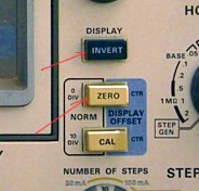 There is the switch to find the zero of the screen. So when you press it, the beam should point to the center of the tube. I needed to wiggle it occasionally and then it worked again. Then I needed to wiggle it more often, and it became a problem. Something similar was with the 'invert' switch, which is needed to display curves with negative voltage upside down, so they look normal again. Such curves for instance for NPN transistors are displayed normal, and curves for PNP transistors are displayed inverted. As these are hidden beneath a layer of other boards, and you need to take all knobs off the whole front, and remove all those connector pins from the boards, I had the idea trying to spray some C60 contact oil in the switches. You can access them a little bit by pulling of the knobs. That turned out to be a very bad mistake, and it was the last time I use that contact oil probably. Initially this solved the contact problem, but it made the cause of the problem get worse. So after 3 years, both switches gave up function. The invert switch didn't toggle anymore, and the Zero switch sticked out 2mm too far and it had no function anymore. So what I tried to avoid, remove all boards, had to be done now anyway, and as I will show later, the contact oil damaged one of the switches.
.
Access to the switches is poor.
Some piece parts can inside and get lost. I decided to take out the whole board.
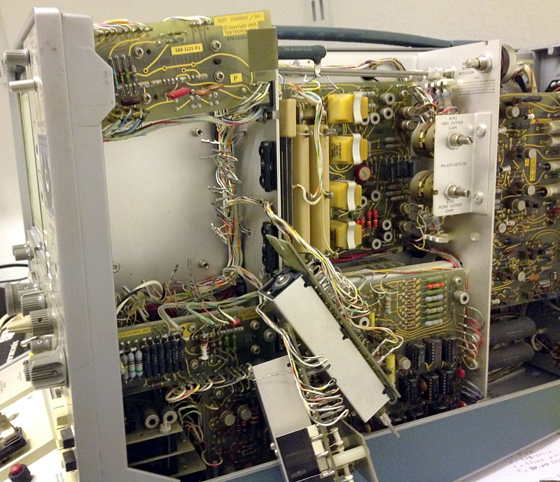
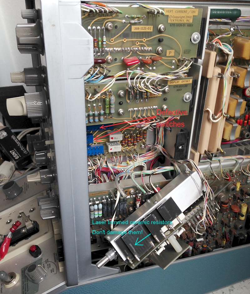
Here you see what boards needed to be removed
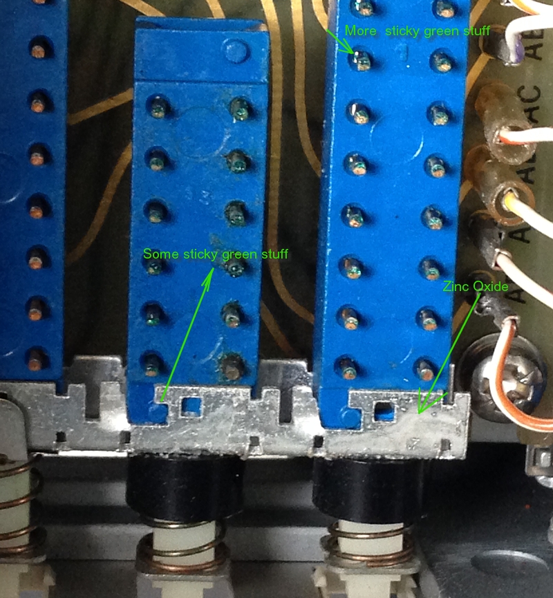
Here you can see the problem. Some green stuff is all over, it sticks like glue .
Also there is an Oxide layer build by the C60 Contact oil.
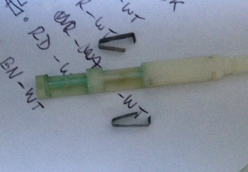
This was inside. The contacts were sticky, and also there was a dark brown layer of something on them,
which was not very conductive. I think I should better not have used C60 Contact oil.
.
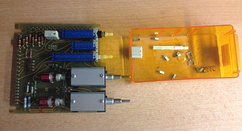
This is the board before repair
What you cannot see, the contact oil has also loosened the bottom of the middle switch, and that made the arm come out 2mm too far. I could clean it, the green stuff resolved in alcohol, the brown stuff would come off with fine abrasive paper. The switch bottom had no great force on it, it could be repaired as you can see on the next picture. I have been looking a little bit for such a replacement board, but it was kind of rare, or too expensive. However, the switches as such can be found still from other Tektronix oscilloscope boards, and perhaps from the manufacturer too, but I don't know who that is. They look kind of standard switches to me. Note, to have more room for the repair, those white cubes are relays and you can pull then out of the board just like that.
.
.
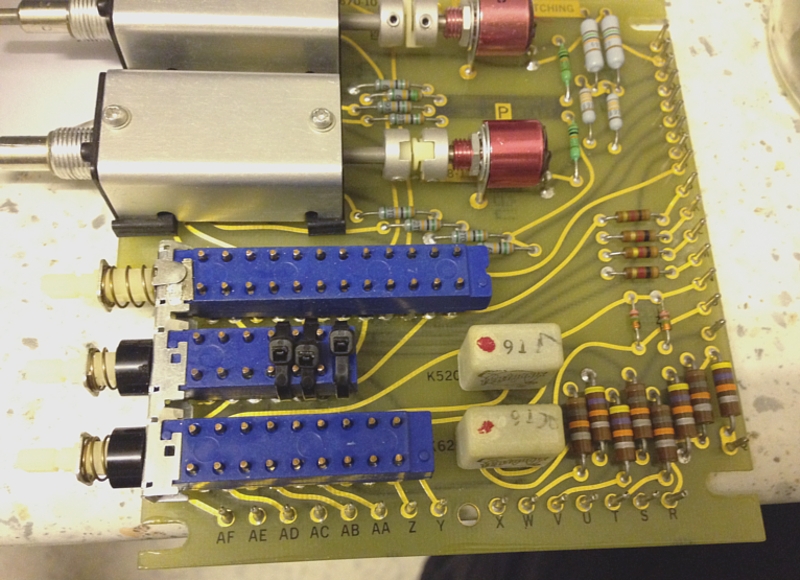
This is the board in repaired condition
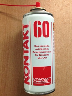

Look at the spray container, the C60 contact oil has created a fat, sticky brown layer with rust. Similar to the green stuff inside the switches.
This is a good place for this FAKE repair item. YOu can use C60 to loosen rusty screws, but not to "Repair" bad contacts with a mixture of acid and oil. Yikes!
REPAIRS: Defective lamps in the readout card.
 The 576 has a read-out card which is made by lighting into fiver optics with a series of light bulbs. This is one of the best features I have ever seen, and it shows what the Tektronix designers wanted to have, but digital electronics was just not ready for it yet. Though developments were very close actually, and right after these readout cards, first ICs came on the market, so called Character Generators, which could display texts on an oscilloscope tube. However, this light bulb solution is amazingly well done, and the card itself is very compact also. Also the cards shows things as they really are. So when you magnify with some factor, the card corrects it's reading. Or the step function (3rd number) can be in mA or in Volts, depending if you test a transistor or a FET. This is done all correct by some arrays to diodes which in the end operate the driver IC's for the light bulbs. You really can't see this is an analog + light bulb solution.
Nice, big indicators, that change their readings with relay clicks, and normal white light. They have build this from fiber optic, and normal light bulbs. There is not one light bulb per dot, but whole groups of fibers are lead to one lamp. That reduces the number of bulbs needed, but there are still some 50 lamps used. So to change from the letter 'V' to 'A', there are thee light bulbs needed. One will light up all the dots (with separate fiber optic cables) that belong to both letters. The second one lights up the complimentary dots to make a 'V', the third one lights up the complimentary dots to make it an 'A'. The driver IC has a diode matrix inside, and the input is just c '1', or logic'0' and 'V' or 'A' will burn. All of this becomes very handy when the 576 is programmed EXTERNALLY. Many are not aware of this option! So when you remove the hand-operated unit from the bottom right, you can replace it by a card unit. The card unit will automatically do the complete settings, and you will see that on the dot matrix display. With some technical skills, I think it is not even difficult to operate a TEK576 from a computer that way. All you need is the programmable module, it had all connectors.
The bottom unit is for the steps. For transistors you set to uA base current, and it gives the Beta. For FETS and Triodes, the steps are in Volt, and you get the Gm. Note, a FET and a Triode are essentially the same for a curve tracer. So even on the very old 570 that was made before FETs existed, you can test FETs.
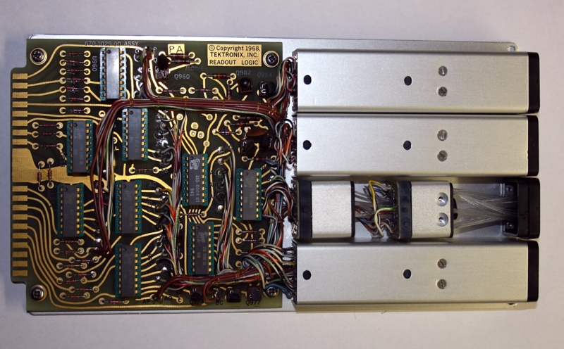
Readout Logic unit with one cover removed, to replace a defective lamp
The card does all the decoding to the dot matrix. So the inputs are just for: 1, 2.5, 5 etc. When '5' is selected, only the dots to build a digit 5 are back lighted by fibre optics, and the correct lamps are selected by the IC's. Have you ever seen gold plated 16 pin ICs?
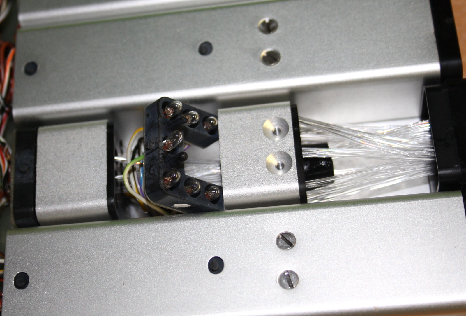
Readout unit, lamps with Fiber Optics unit. (click image to enlarge)
There was a lamp defective in this unit. Curiously it pulled 50% more current, but no light. After testing, it appeared to have lost vacuum. So the heater wire gets too cold from the air, doesn't glow anymore, and current is too high. I was able to find some original replacement lamps. (ask if you need one).
Somebody replaced a light bulb, but he was not very good at soldering. (This work was done by university of Houston).
Not pictured here, but this soldering I repaired too, though it was electrically good. The broken lamp was probably suspected here, but it was one of the adjacent lamps that was broken. This must have confused them, and they didn't solder on the broken lamp anymore. Well admitted, this was a difficult defect, and the unit works confusing indeed. Here is a typical case of somebody not getting any further, and put it back together for the next person to try. Well that was me.
Look at this hardware quality, all the gold. It is probably very thick too.
With older equipment, when soldering begins to detoriate in general, lots of trouble will come your way. Not so with this beautiful soldering quality from Tektronix. This is the lamps driver IC, when you pull it out, you can apply 5V to the outputs, and see what lamp is broken. So in this picture between the brown wire where it says 'AP' and the IC outputs 9...15 you can apply +5V and that will light up one of the lamps. Some lamps give funny patterns, and only the right combination of lamps builds the symbol. So the IC's have some encoding logic inside, and the lamp drivers. So we have an all hardware dot matrix unit here, made with light bulbs. May sound primitive, but on 1968 there was no other option. And really with the white light and brilliant sharp symbols, it is very well done and very useful. I think this was a little bit an art project of the designers also. The readout card was expensive and optional. I guess it's still expensive today on Ebay.
It is interesting to observe, at the same period this read out card was designed, they designed the first digital read out systems at Tektronix as well, but it seems that technology did not make it into the 576. Later versions, the programable curve tracers, used the bezel design of the 576, almost unchanged, but the bezel covers now the right edge of the CRT, and from behinf there, the same numeric information is produced by the CRT and a digital read out. Frankly, I am glad they did not add this "improvement" to the 576, because it would have made the useful area of the CRT smaller, and the white incandescent light bulb + Fiber Optic read out is so excellent and clear to read.
REPAIRS: Example of a cracked knob.
This long term damage occurred, because the inside metal part is pressed into there with great force. No good idea for plastics. This seems to happen often, so old knobs are expensive on Ebay. I repaired this knob with JB Weld, which has the same gray color. You can hardly see the repair. So no need to pay 25$ on Ebay.
Sunburn is on many plastic parts, but it came off just by using it shortly.
This proves indeed it was not used for a decade, but it was in the daylight still. Well, better like that, as in the garage for 30 years. You can see the many scratches on the CRT cover too, but these are actually plastic plates that you can remove conveniently and I machine polished the scratches away.
Some versions have no read-out unit. The read out unit is so wonderful, I would not want to have a 576 version without it.
The Quality of the components inside.
At this point, the 576 differs massively from the 570. The 576 is a new generation of products. The change was made from hand soldered technique, to printed circuit boards, and not just some boards. The PCB's are glass fiber and gold plated in my 576. Augat Brand IC sockets everywhere, and many gold plated IC's even. Though I have seen some from Italy without IC sockets, and without the gold plating. As these sell probably for the same price, make sure you
REPAIRS: Cardanic Axis
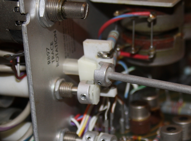
Cardanic Unit broke off. This is from the scope tube brightness. It's crazy but I could just buy original old replacement parts in Tektronix packaging on Ebay. (see below)
Another one broken. This is from the looping compensation capacitor, to the front panel.

1977 NOS replacement parts on Ebay from Greece. Two for 8 Euro. Just what I need :)
REPAIRS: The 5V power supply.
With respect to the Tektronix designers, but the rectifier circuit is strange. The output signal is 5V DC, 100mA to feed 6 TTL IC's. Only 100mA, and they are using a big chunky capacitor of 11.000uF, followed by a series regulator, with a heavy power transistor. Very bulky, and I am sure this could have been done with less parts. Or perhaps it was right after all, read below under ESR meter. Such things do contribute to the massive weight, and I see this philosophy, that 'cost, weight and size play no role', throughout the whole machine. But let's not criticize Tektronix for that, because any 50 years old equipment with savings on material cost, too simple circuits, and too small build, are not fun to work on.
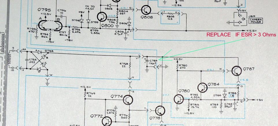
In my 576 was a defective rectifier capacitor in the 5V electronics, and the regulator circuit worked very strange. I had a hard time finding out what the heck caused all of this. Whereas in the end this is only a 5V 100mA power supply, feeding 6 TTL IC's with 5V. Well I was lucky, the output voltage was too low. It was 4.2 Volts. When it gets too high it damages the ICs, and they are hard to substitute. Later I learned, other people have the same problem. So when you buy a 576, check the 5V circuit not just to be nicely 5V, and also check for no ripple on the input. As a good 11.000uF capacitor will give no ripple at 100mA. I would say, it is better to check the all rectifier capacitors with an ESR meter (of the kind you buy for 20 $ on Ebay, they work very good). ESR = Equivalent Series Resistance of the capacitor. You can call it Ri if you like. I found it to be in the range of 0,8...1 Ohms Ohms for all power supply capacitors. (apart for the broken one).
The use of an ESR meter
ESR stands for Equivalent Series Resistance. Such a meter cost only 20$ on Ebay, and these get more refined every year. Originally a Danish designer made an Arduino design with this, which worked excellent. He published the code for public use. I made a copy of this long ago. Later, some Chinese said thank you, and took it into production. They improve the graphic interface, but I think not it's functioning. So at the moment you can buy those with a color screen and much better graphic resolution that the first ones. The test routine seems unchanged ever since. All of that for just 20$. Such a meter first ramps up a very small voltage to see what happens. When current begins to flow, it does some other tests, to find out what might be connected, and it continues until any three lead device is identified, and tested. So much better than any 800$ Fluke, which pumps 1mA (at 9Volt open circuit) into any unknown device, that can really damage anything. The ESR tester also uses a low voltage, low current oscillator signal, and it measures current + voltage. When all tests are done, the software can say if it found a diode, a transistor, a FET, and keep PNP and NPS apart. Measure a .resistor, a capacitor, a short, a battery, a zener, or a normal diode, and tell the value. If a capacitor, it will give the value, and the equivalent series resistance. The nice part is, you can leave the capacitor in the circuit, and due to the low signal it doesn't damage any semiconductors. Don't worry about how this is done. The point is: It works. So you just connect it to a capacitor in a circuit. Suppose it is printed on the capacitor: 8000 uF. The ESR meter will detect at the connections for instance 2000uF and 100 Ohms ESR. So definitely this capacitor is bad, though it will have some function still. Or, when it says: 6000uF and 5 Ohms, it is still good. Of course this is not a 100% sure test, but to my experience you are close to 100% in all practical circuits. When ESR is too high, the capacitance itself is too low, that comes together in case of detoriation. When ESR is too high, but capacitance still good, the capacitor has a contact problem inside. For all easy to remove leads, I did solder them off still, and then you can test any capacitor precisely. However, as I said, most of the time you can find the bad capacitors in the circuit, because normally ESR is too high then. ESR should be a few ohms only. There are tables for that, but this approach is relatively new, and I rather compare it with good brand capacitors of the same kind. So you cannot compare an bulky 5000uF cap from Sprague, with a Chinese one, and you wonder how they can make them so small and so cheap. . The answer is found in ESR changing already after a few years of use.
A very useful application is test capacitors you would not necessarily test, because they are somewhere on a PCB which works good, and you don't want to damage something. Even new capacitors don't get any better from soldering them in, but de solder 50 years old capacitors, and solder them back in, is not what you should do without need. Then they have been soldered three times instead of only one. WIth an ESR meter, you can quickly test every capacitor and not desolder it. If you never worked with such a meter, spend 20$ on it, and it will change the way you work on broken equipment for ever.
Still, because one appeared bad, I decided to I de solder all capacitors of the power supplies. There are two PCBs, mounted over them, and you need to remove those, by unplugging the connectors. Also take your chance to correct the connectors a little bit, as some of them got a bit loose ever since 1968 when it was made. My ESR meter indicated all capacitors 'like new' except for C759 of the 5V supply. It had so high ESR, it was regarded broken. Other 576 users report C759 broken as well, so it is a common fault error. I opened it up so see what's inside, and it was very wet still. So sure not dried up. Still ESR was 'infinite' on the tester. So this is really interesting to see, so many of those old electrolytic capacitors were still perfect ever since 1968. Here comes a point, all good electronic designers know: Lifetime of electrolytic capacitors increases drastically when you have a low AC ripple current through them. So with this power supply, perhaps also 1/3 of the capacitance value might have done the job as well, but then ratio of ripple current and capacitance would have been '3 squared' higher, so 9x higher, and lifetime would have been even more drastically reduced than a factor 9. There are tables for that, in any capacitor meant for power supplies, and you can bet those guys at Tektronix knew how to test capacitors with their own curve tracers. So on the one hand, the capacitors seem extremely over dimensioned, but on the other hand, what is sure, almost every one is still good now ever since.
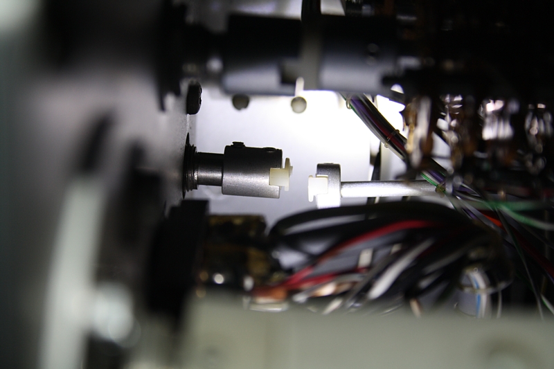
 To remove the capacitors, first you need to pull of the plastic cap, by hand. To get the capacitor out, you can do this from the visible side, but you can't get the screws back in for the replacement. To do this, you can carefully take out the small High Voltage box. No need to remove the oscilloscope tube. Hint: There is one nasty screw that you can't get out easily. Use a normal, flat screw driver, and then it works. You can use that under an angle. Like this I could remove the screw, slide out the box, and reach the capacitors from the other end, with my hand inside. I was able to fit new capacitors very easily inside the cap of the old one. Just saw off the cap. It was almost no work, and result was perfect. You can hardly see the repair afterwards! After I did this, the 5V supply was good again, the digital step generator worked, and the 12V circuit worked better also. Don't know exactly how, but the different voltages relate to each other. Like the 12V circuit produces the reference voltage for the 5V circuit.
.
Power supply caps can be reached after removing this small unit.
.
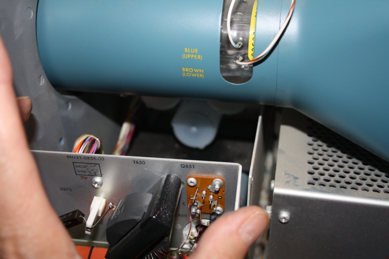
This picture was send un 2022 by Robin Chatterjee, after repairing his 576, with the same error. Here you can see the 5V collapsing due to the capacitor not having enough capacity any more
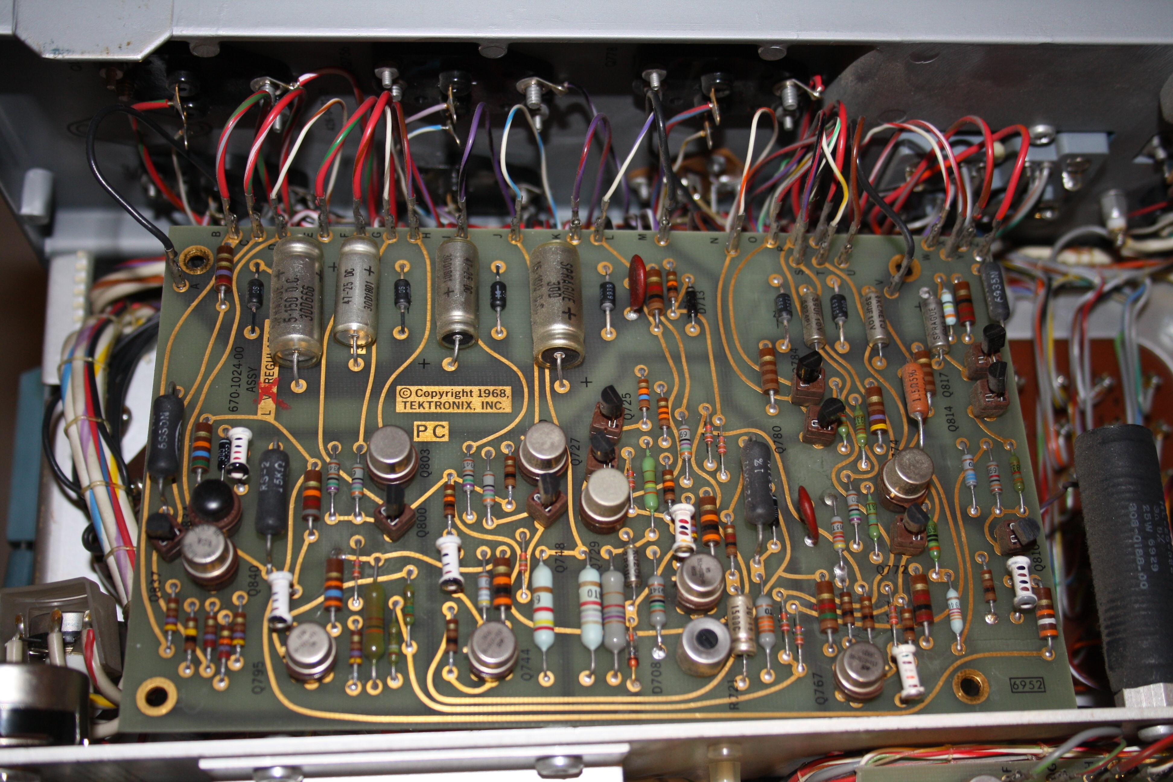
Power Supply board. Diode board is underneath.
All ok, nothing to say about it.
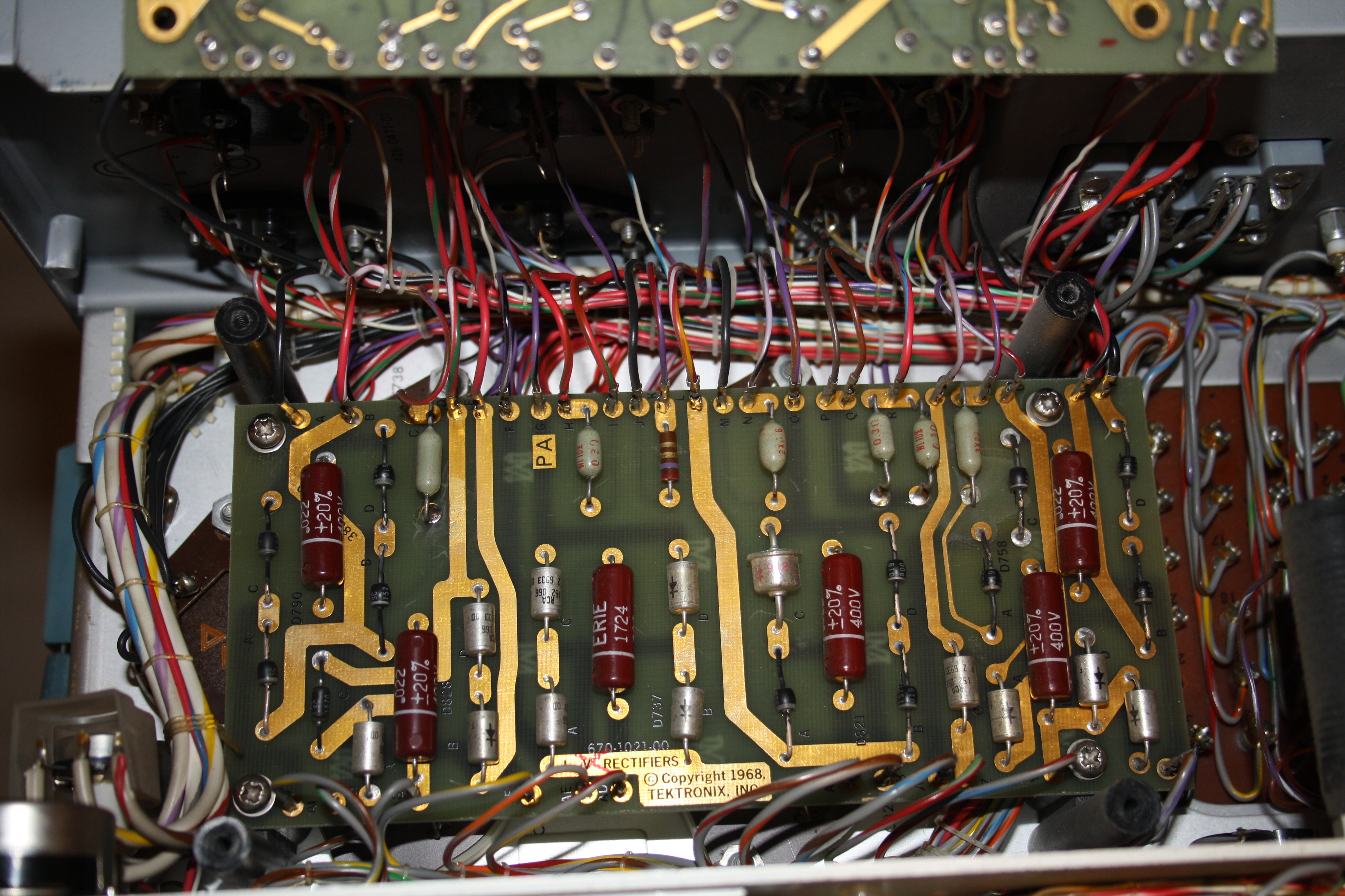
Rectifier board. C759 is underneath. All diodes give in-circuit 680mV with my ESR tester.
Look at all that gold, it must have been cheap in 1986.
All in all this whole power supply is a strange thing, and I would not have made it like this. I would have created the +12V with a 5 Volt 2Watt Zener diode as a reference. Then, take 100mA from the Zener diode to feed the 6 TTL ICs with. As simple as that :) But ok, 1968 is a long time ago. In the 1980's I was one of those myself, and I remember this atmosphere exactly. Things were different by then, designers liked to present fancy circuits, kind of showing how clever you are. Those guys were the kings in the electronics design department. I am sure, older analog designers know what times I talk about.
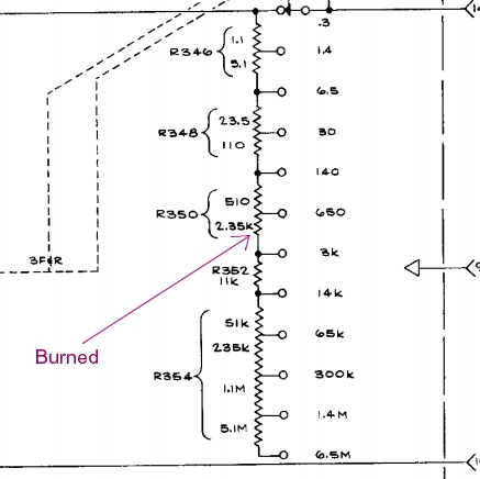
Series Resistors. The high Voltage to the device under test has a series resistor, limiting the power into it. 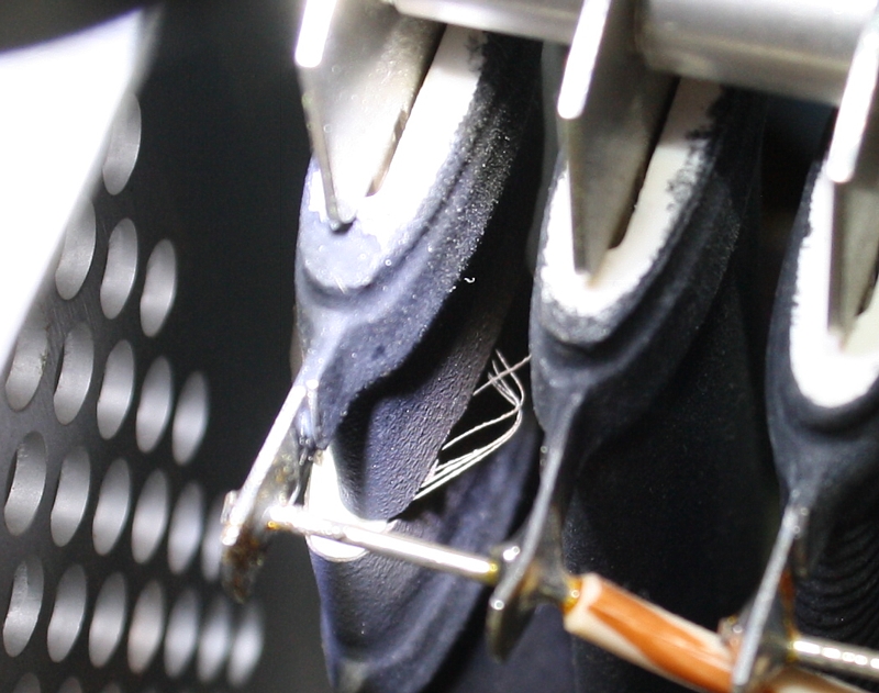 While I was testing a power supply choke, one of those series resistors went up in smoke, when I went from 350Volt to the 1500Volt setting. I can't say much about this yet, first I want to replace it, and then repeat the measurement. It was not because of choke saturation, as the Lissajous diagram was a nice circle when it happened.
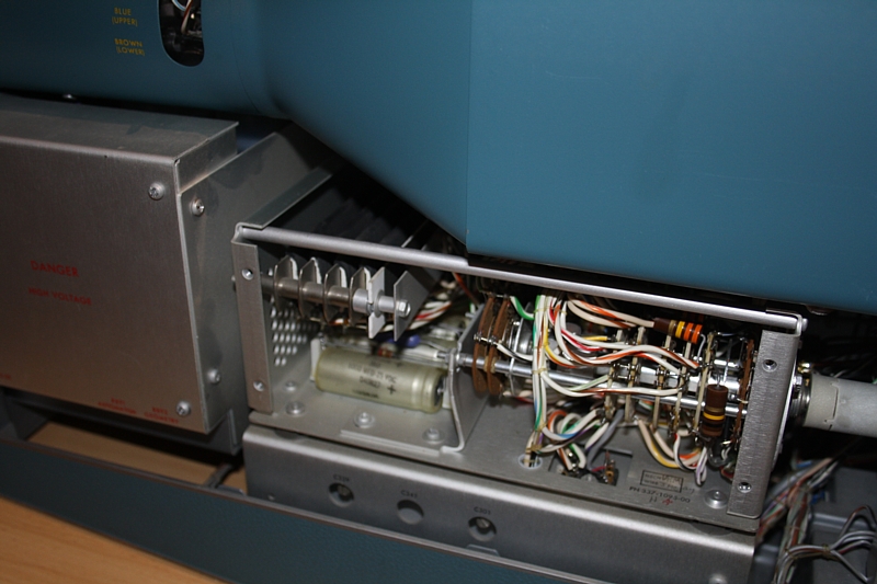
This is the power unit, with it's cover off.
On the left are the series resistors, with a thermal protection mounted on it. Note, the inside chassis is nicely sprayed in Tektronix blue. This is waist of money and resources if you ask me. But as I wrote before, 1968 was another time.

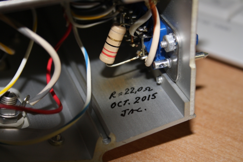
The replacement resistor is 2x 4700 Ohms in parallel, giving exactly that strange value of 2350 Ohms.
There is not much room in there to mount it, but I think I found a good place. As an engineer I really disagree that they mounted those five heater resistors directly above an array of electrolytic capacitors. Well... nothing is perfect.
REPAIRS: This looks to me like a Design Error in the Step Generator?
The step generator has the nasty habit to skip a step sometimes, and it began to get worse, until in the end only every second step was displayed. I found a very nice article about this error on a German website, which made it a lot easier for me.
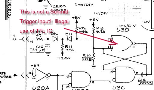
Looking at the schematic, Integrated circuit U3 is nothing but a quad NAND gate, type SN7400, for which normally other symbols are used than the ones here. I suppose, the designer wanted to emphasize the way these gates were used, by presenting it like this. So yes, an AND gate with inverted inputs like U3C has the same truth table like the NAND gate U3D. But I still don't see the use of this strange way of drawing it.
But what I do not like, is the input pin #12, of U3D is presented the edge of an analog signal. So the charge/discharge characteristic of the network, created by C14, divider R13/R14, and the output resistance of the U3C output. If THAT gives the minimum required speed? No, it doesn't.
Does that create a problem? Well, perhaps it does in my TEK576. Now I remember the early days of using SN7400 myself. It was "the" IC, all students were playing with, by Texas Instruments, and we did strange things with it, like making oscillators, and it worked. Later, these circuits, might fail when next generation faster ICs were used, such as LS Schottky or HCT (high speed CMOS) versions, 74HCT00. Reason is simply, there is the forbidden zone of the TTL input signal. Of course you need to pass this zone when switching from 1 to 0, or vice versa, but you must pass it with a minimum speed. In all other cases you need to use the more expensive IC's with Schmitt Trigger input.
So I have to say, I do not trust this circuit, because it's illegal use of the SN7400. However, due to this extremely curious circuit, they cut off the 'undefined' phase, and what comes out is indeed the needle impulse for the step counter. However, the needle impulse is analog. So the edges are not steep enough for TTL. And now the problems (perhaps?) begin.
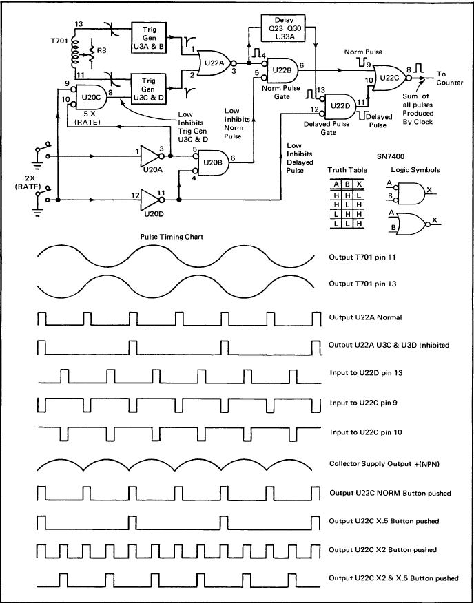
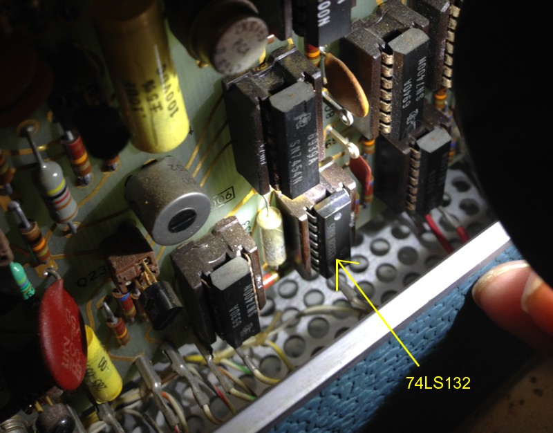
So look at the inputs of U22A. There are two analog needle impulses there, with some very small phase shift, and the result is a small (now digital...) needle on the output of U22A pin 3. The analog signals on pin 1 and 2 However, may sometimes cause a second impulse on Pin3, and that causes a failure with the step counter. After replacing U22 (SN7400) with an 74LS132 the problem was almost gone. 74LS132 is a quad NAND with Schmitt Trigger inputs. I am not so extremely happy with this, because I do not know the reason why they made this illegal use of the SN7400. Was it ignorance or did they do something extremely special? We won't know. The machine is from 1968 and the designers probably don't work there anymore. In case somebody has more information, please let me know.
When I have more time, I want to see how R8 needs to be adjusted in order to get the best needle impulse at U22A pin 3, and check what is the change when going from SN7400 to 74LS132m, as logic levels of 74LS132 are not the same. Because it's LS, and because it's a Schmitt Trigger.
.

Burned resistor in the test fixture. This was not me!
This was the collector 'sense resistor'. I selected a very precise one.
WARNING: Later I learned how to burn those resistors. There are two in there, one for each position (left-right) of the fixture switch. I received my 576 with one resistor burned, I soon burned the other one myself. This is how it happened: On the text fixture is CBE for transistors, and two additional holes for whatever it is. When attaching a device to those two holes, you can nicely do AC measurements on it. However, when you try to test a high current device there, those 22 Ohms resistors go up in smoke. High current testing I do via the Collector-Emitter terminals, and then it works fine.
CALIBRATION OF THE TEKTRONIX 576
Of course you need to use the original calibration procedure, and ideally you own the calibration fixture. Here is just a short cut I took, and it seemed to me it was within calibration anyway, apart from very minor adjustments in the 1% range. Also if you find, calibration is totally bad, you need to look for other things first before you mess up the rest. Like one of the internal voltages is wrong, or something with CRT tube. So never try to 'calibrate away' a problem, without fixing it at the root. I know people LOVE this method, but I hate it, as it never made me happy. So any problem, find the root cause first, and fix it before calibration.

.
Here is how I went, but again this made only sense as the machine was pretty good condition anyway. If it is full of problems, better fix first these issues one by one, and do not waste time on calibrating an instrument with problems inside.
.
Building a tube tester interface for the 576
The 576 was never intended for tube testing, but it fails only a heater supply.
As you can see clearly, at Tektronix they must have thought the days of tubes were over at that time. Well we all thought that, though it was wrong. It is a pity, because for testing triodes all it lacks is a heater voltage. This can all be simply added to the fixture with two banana plugs and an external power supply. Probably the superior versatility of the 576 will allow some testing options, the 570 cannot do. I expect to find that out later, and will update this page when I know more.
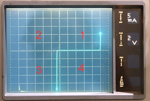
On the left here you see the Quadrants. These are numbered in electronics counterclockwise, for whatever the reason. Here you see zener diode tested. So the forward voltage is in the first quadrant, with positive voltage and positive current, whereas the Zener part is in the third quadrant, with negative voltage and negative current. These kind of curves are displayed in the 'AC mode', so for testing two lead devices.
Three lead devices have a control input, which the 576 can supply either with a voltage or with a current. So you see, this is already something the 570 cannot do, but a control current may be interesting when checking positive grid voltage driving a tube. Just to name something. Also the 576 can produce a sweep with a negative voltage. This is interesting perhaps sweeping the grid voltage, and stepping the Anode voltage. Or work with a higher external anode voltage and show al least one curve. So this would show a 2nd. Quadrant curve like this. Though I really have no idea right now if this will be possible, and I want to look at such options all on the end of this project, and not at the beginning.
Things to take care of, when testing tubes with the 576
- Interface. There are three connections on the interface board. C, B and E, for Collector, Base, Emitter. Now FET's are simply connected there as well, and tubes also. Just have have set up the tube tester for the right kind of sweep direction. So referring that to a transistor it means, we need to set the 'PNP-NPN' switch to NPN, or (which is the same) to the '+' sign. That will give a positive voltage sweep.
- Grounded Cathode. We want to test the tubes normally with a grounded cathode. So choose 'grounded emitter'. Though of course you can choose grounded grid as well (choose grounded base), but I have no purpose for such a curve The 570 and 576 can do this just re-ranging the leads, but 576 can also do this with the selector switch. Well at first I am only interested in plain, normal triode curves, so the ones you can see all over the internet. These are in the first quadrant, meaning a positive voltage sweep.
- Heater Voltage. The 576 has no external heater voltage of course. We need to heat the tube under test with an external AC or DC power supply. When using AC, there is a complication when testing Directly Heater tubes. We need a centered connection on this AC voltage, which becomes the cathode connection for the 576. I tried it without center connection, but that doesn't work at all. Reason is, the anode is sweeped with 50 (or 60) Hz, same as the heater voltage. However, with DHT tube, the virtual cathode is always to be thought as the center of the heater. However, that virtual cathode is now sweeped with the mains frequency as well, and that messes up the tube curves. When using DC, there is no mess with the curves, but the virtual cathode stays always the center of the heater, and this virtual cathode is not grounded. This creates an offset of half the heater voltage. Also with DC, we need to work with a center tap, so two DC power supplies are needed for DHT. For indirectly heated tubes, this doesn't matter.
- Screen Grid voltage. For testing pentodes, we need an adjustable screen grid voltage. This a small current power supply only, but we need it. Perhaps it is a an idea, to derive that DC from Anode voltage, using a resistive divider and a potentiometer, and design this circuit such that the screen voltage is always lower than the Anode voltage. It needs to be tapped at a point inside the 576 before the anode current is measured.
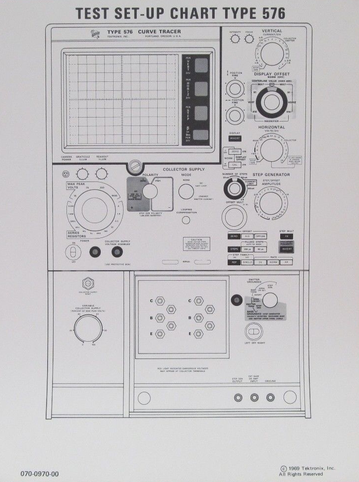
This is to copy and print. You can color mark specific set ups on it. Some wise guy sells printed
Versions of this on Ebay and sells it as 'cards'. (it's just a copy from the manual, but he seems
to get 7$ for one)
So far for the repairs, and my TEK576 is in perfect shape now.
Conclusion: The Tektroniix EK576 is a highly recommended, extremely useful machine.Well it took me three weeks to restore it, every day 1 hour, but it was fun doing. What I can tell you, having a curve tracer really makes you understand two-lead devices better. As far as transistors are concerned, it amazed me that Germanium transistors have much nicer curves than silicon devices. I always thought they were 'primitive' or so, with bad curves and lots of distortion on it. Also, curves of those 'primitive' OC71, AD150, AC126, they were all so nice looking, and actually a LOT better than all pentode curves I have ever seen!
The Tektronix 576 is so nice build, it is unbelievable. I would not know what to improve, apart from the weight which is really crazy.
Interesting idea: but I am not going to follow up on this: If you buy the programmable fixture on Ebay, you can access all connectors and wiring to control the TEK576 by computer, using some USB relay cards. May be you don't know, but most settings are relay controlled anyway. So when you choose 20V per division, it's just some relays you operate, also when you use the rotate knob. The knob itself doesn't do the switching, but it switches the relays. WIth the programmable fixture you can access all those relays yourself.
Loose items, unsorted
- Prices of the TEK 576. From what I found, it was it least build for 21 years from 1969 to 1990, and last units were sold from the 1990 stock, in the year 2000.
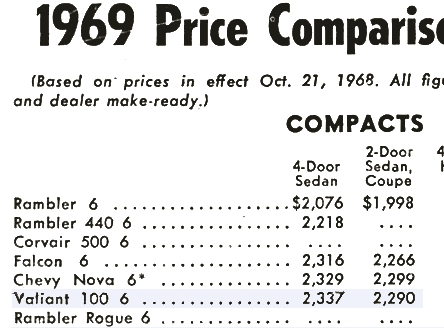
- In 1969 it was more expensive than a Chrysler Rambler 6-Cylinder, two door Sedan Coupe. In 1990 it was sold for the price of a Mercedes Benz. It seems as if they tried to stop sales of it, by price increases, but that didn't work.
- Also what we are seeing (as I write this is 2021), the prices of good 576 have gone up a lot. For a long time, they were sold as heavy weight crap for old fashioned idiots, but today with the hype around those cheap pulse testers for electron tubes, more audiophiles begin to get interested in a REAL TIME tester, and no.... that does not exist from new production. Itseems to me, prices have tripled over the last five years.
Catalog prices:
$2125 (1969)
$2800 (1973)
$5200 (1977)
$8775 (1982)
$11455 (1985)
$17050 (1989)
$18440 (1990)
- Some specific parts of the circuitry works relatively difficult. It seems to me, the designers had great fun, trying to invent smartest possible circuits. Which is good and bad. What is good about it, such circuits WORK, as they are made by people that know the classical circuits, and then try to outdo them. What is not so good, when there is a defective part, you will spend a lot of time finding out how the 'clever' circuit works, which is very difficult when the circuit is malfunctioning. So you have funny signals on a funny circuit, and that can give you quite an head ache. Well, the good thing as I said before, the used parts are generally very good, and nothing much seems broken anyway. The machine is well build from very high quality material, well designed, and made with good consideration somebody needs to be able to service it, and take it apart.
- Mechanical parts contains plastic parts that detoriate, or becomes cracked. However, real problems from cracking plastic part are small, and it seems replacement parts can be found still. Even the plastic Cardanic connections for the pot meters, that can only break off, I found some NOS replacements on Ebay within minutes, and they were even cheap.
- Weight is crazy and simply sick. They really took no effort at all to save on weight. So you will see two pot meters in the back, connected with 30cm long metal rods to the front, using Cardanic coupling pieces, and the pot meters mounted on thick aluminum panels. Protection caps on the internal high voltage units are from (too) thick metal, etc. Everywhere you look, it's twice the weight needed. So in the end the whole item gets twice as heavy. You can hardly ship it. So beware, you cannot put this in a card box. This needs a wooden palette to ship. If the post man refuses to hurt his back, and simply drops such a box, I wouldn't blame him. Please consider this a real problem for yourself, when you are not strong enough.
- Lamps are expensive. The 'type 349' lamps that illuminate the scope are expensive, they cost 2...8$ one on Ebay.
- The red hazard lamp on the right burns when test voltages exceed the maximum of 15 Volts. So far so good, but if this lamps breaks, there is a safety precaution switching down the high voltage. They used the safety switch of that, so the one that is underneath the Test fixture. There is a relay which only is 'on' when the switch of the safety cap is closed. However, when the hazard lamp itself is broken, the tester behaves as if the safety cap is still open, which by itself makes the yellow warning light burn. You can try that out, just set up a test, and while it's running, pull out the hazard lamp. The same moment the tester shuts down. So yes, really safe, and at 1500 Volts, that is a good idea. On the other hand, I wonder how many 576 were send in for repair, because of this. This behaves like some defect with the high voltage, it refuses to switch on. So you think your 576 is defective, but it's only the hazard light bulb that is broken.
- The fuses are at the back. There is also a thermal fuse inside on the high voltage series resistors, which will reset after some time. You can choose from a low, medium, or high mains voltage setting. So save the instrument, best is to take the lowest one.
- The high voltage for the horizontal sweep, up to >1500 Volts peak, is generated with a variac, and actually they use the sine wave of the mains voltage to do the horizontal sweep. The nice part is, you cannot damage this circuit so easily, it has a thermal break out, which you can re set. By using the variac you can conveniently ramp up from 0 to 1500 Volt, or whatever maximum you take. Also there is current limiting on this, by an selectable series resistor bank. This is strong, safe, effective and will take some amount of abuse and errors.