GM70 Dual mono block amplifier.
Using both Parafeed and Sakuma principle
Description
Disclaimer: Please understand we have to say the following for legal reasons, but we do have to say it. Otherwise we get held responsible for errors of people want to build a HIGH VOLTAGE tube amplifier while learning by doing, and do not realize that trial can result also in error, with dangerous situations. So we say this clearly up front here: This is only a report here, about this (wonderful!) project, and for legal reasons we claim this is NOT to be an instruction about how to do this safely on our responsibility. So if you decide to re-build this project, we sure help you out with questions and issues if there are any, but whatever you do, you should have full understanding yourself of risk and safety related to it.
So when we write "you have to do this, and you must do that" this is only the way the text is written, but the text below is still only a technical report only. I hope you understand why we say this.
So if the above text shocked you, consider it's better to be shocked by a text than by High Voltage :)
For those who know how to do this work safely, this is an interesting project. This GM70 Amplifier has some amazing advantages. The technical details are explained below here, but the idea was also to construct things such, that testing can be done, block by block, and function by function. Like this, risk of damage and problems is reduced to a minimum level. Here are some examples, which you initially may not realize, but are to my opinion very helpful. So once more, the below text for legal reasons is only a description of how I would do it myself, and only that.
RELEASED AND TESTED GM70 DESIGN
Some words about Mr. SAKUMA (picture below)
 Mr. SAKUMA, lived from 1943 to 2018, and was the owner of a must curious restaurant named Concord, in the town of Tateyama, Japan. In his small musical restaurant, which he managed over 40 years, he served only one single menu: A Hamburger, Japanese style, but a visit was sure not boring. The guests were asked for their musical preference, and also with what tube amplifier this music should be played. The amplifiers were nicely in a wooden cabinet, ready to play, and those were all those famous 'Sakuma' amplifiers, of which you find some schematics via the internet. His favorite way of listening was mono recordings, using a Denon DL-102 cartridge. Such a nice way to give meaning to those products and use them every day. Mr. Sakuma not only had this unusual place, but also the way he constructed the amplifiers was very unconventional. It seems like a farewell to theory, but in terms of theory, he knew actually very well what he was doing, and his designs used very interesting driver stages. He was very well known in Japan. His jazz restaurant was shown on TV, he has published over 40 articles in the first class magazine MJ Audio Technology, published a book, and was working on a second book.
Mr Sakuma was famous for driving transmitter tubes like 845 or 211, with the same tube, and same configuration, to cancel harmonics. He published this specific method in Japan in the 1980's, and later also in Sound Practices in 1997. I found out, he is not the inventor of this, I have found theory also in my "Ratheiser" Books 1950. In case you are interested to buy those, I have the original four bands series for sale, in German language. Yet, Mr. Sakuma was the first who used this method for HiFi. Also in a book of Rainer zur Linde († 2012) , I found the explanation of this harmonics canceling theory, using the AD1 tube in an example. Yet it can be used on any Triode, but best result you will have with directly heated triodes.
I prefer to call this method, the "Sakuma" Method, and this word was chosen by myself, in honor to this special person, and his many beautiful designs. It is nice to see that people are beginning to pick up this word, and I would encourage everyone to do so. I cannot explain it quickly in a few words here, but I will try. I did not believe it myself at first, because theory seems a bit unusual.
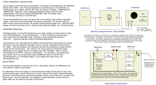
Then, from my own measurements, I can confirm: Yes, it works indeed! This is so amazing and so satisfying to make the harmonics visible on the oscilloscope screen, and see the distortion disappear for the great part, by just setting the bias of the special driver stage exactly right. For this, you can use a distortion meter, or real time Fourier analyzer, this all comes down to the same. Myself, I prefer to show the distortion simply by means of a two channel scope, by simply feed the input signal to Channel A, and the output signal to Channel B. Then, all you need to do, is invert Channel A, and add this result to Channel B. So the scope is set to 'A+B' mode. Since A is reversed, the effect is -A+B. Like this, you would get a straight line (no signal) if A is exactly equal to B, meaning no distortion. If there is any distortion, there will be some difference, and you see it right away "as it is". If you have a two channel scope, this a thing you really should try to do, because it needs no other equipment, just the oscilloscope itself. The nice part of this method, it is real time, so you trim the driver stage, and you can see immediately on the screen what that does to the distortion. Also you can change the frequency, or amplitude, and immediately see what what happens. Also the fact that distortion is always "harmonics" gets impressively visible, because you will see the result is mainly second harmonics (so 2x the frequency of the input signal) and a very small fraction third harmonics. So just on a normal scope, and nothing else is needed.
The following I never tried, but with the right set up of an attenuator, and a few additional parts, you can create an A-B signal from any amplifier, derived from it's left channel. Then, this sound, or rather the distortion noise, you can feed into channel B, and listen to it. That would be the sound of the distortion itself. Feeding a 1kHz signal into it, would result in a mixture of 2kHz, 3kHz, etc. That would sound like a distorted guitar of twice the frequency. When feeding not a single tone into it, but voices or music, you would hear the distortion only. Which is not recognizable as the original any more, because that's for full 100% not what it is. If the amplifier would hum a little but, you would also hear the hum. Well... perhaps I have to try this.
Often I get questions from people who are interested in Sakuma amplifiers, puzzled by the magic of it, but they do not fully understand how this is working. So I recommend to read the following compact part about distortion theory. Well, skip this part if you already know it, but without this you will not understand the Sakuma principle. So it is important.
A little something about distortion theory.
This is an interesting subject actually. There is amplitude distortion, phase distortion and run time distortion. With amplifiers, usually all types of distortion appear together. So when you reach the frequency point, beyond which the amplifier begins to distort, you will see amplitude and phase distortion appear together. Also it will appear in the same order of magnitude. So when the amplitude error is only small, the phase error will also be small. Or, when amplitude begins to drop very much, phase error is large too. Now this does not have to be so per definition, but with tube audio amplifiers, I found this is always to be the case. Which makes life easier for us, when we want to build a good tube amplifier. If the amplitude error is low, phase error will be low by itself. Whereas run time distortion is rather a constant with tube audio amplifiers, meaning we can ignore it for non-feedback type of amplifiers. (Note: for amplifiers with feedback, a delay time can cause nasty effects). The Sakuma amplifiers use no feedback anyway, so for those we need to look only at amplitude distortion, and all the rest will be fine.
There are two kind of distortion that interest us:
First, there is linear distortion.
This is like coloring of the sound, same as a tone control will do. It is logical when you put two tone controls in series, you can increase the bass volume with the one, and attenuate it with the other, so the effect is zero. This brings us to an important property of linear distortion: It can be reversed. Something similar is done with RIAA correction, so the record is recorded with too lower bass signal, in order to make the grooves easier to follow for the record player needle. Then, the RIAA pre amplifier increases the bass volume again, and the result is neutral.
Second, there is non-linear distortion.
This means trouble, because it means adding frequencies to the signal that were not there before, or removing frequencies from the signal. It is obvious, when frequencies are removed, this is permanent. When frequencies are added, it is only possible to remove them, when we know WHICH frequencies were added, and at what amplitude and phase relation. Which information However, we cannot derive anymore from the signal. This brings us to an important property of linear distortion: It cannot be reversed.
Once a new frequency is added, it is not possible to remove it anymore. The added frequencies we call harmonics, because they appear as nice multiples. So if we distort a tone of 1000Hz, frequencies of 2000, 3000, 4000, etc will be added. So this is non-linear distortion, and the added frequencies are the harmonics. Until a small level, even harmonics are no problem for the human ear. They are desirable until a small level only, and we call that tube sound. Uneven harmonics however, sound always bad.
What can we do against distortion?
There are only two cures: Compensation and Feedback.
Negative feedback is the most commonly used, because it works well, and it is cost efficient. However, negative feedback removes the natural sound from the amplifier. Mathematically speaking, the electrical properties of the amplifier become the inverse of the feedback network, this is very important to understand. So from school books of amplifier design, you can look up the section on feedback, and it's calculations, and the gain becomes simply the inverse of the feedback attenuation factor, which is a 'number', and all amplifier characteristics are eliminated from the equations. This makes the amplifier sound sterile indeed, the more feedback you get.
Reason is, negative feedback removes everything which comes from the amplifier itself. So really all that is left, is this: Output Signal = Gain x Input signal.
Whereas a non feedback amplifier has the desired (very complex) interaction of the loudspeaker chassis with the power tubes, via the transformer. This works in two directions, so from the output tube, thought the transformer into the speaker, but also the speaker is DAMPED via the output transformer, by the plate resistance of the output tube. This, and many more elements make the non-feedback tube sound. Also driver tubes and pre-amplifier tubes add their specific own components, called harmonics. These are all very difficult interactions, having nothing in common with a feedback amplifier.
What is negative feedback? By subtracting the input signal from the output signal, at first the "error" signal is created. This signal would be zero if there is no distortion. The error signal is then added to the input, but in negative phase. This eliminates a great part of the distortion. The electrical signal transfer of the amplifier begins to behave more linear, the more of the error signal is added, but on the other hand it sound less as it was originally. It makes the output stage behave more ideal, the more feedback is added. This is why people who are looking for specific tube sound do not like negative feedback. That is why another method of linearization was used here, it is called compensation.
 Compensation is another method to reduce distortion. It means we generate with separate electronics, the error that we believe the output stage is going to produce. Then we add this error in anti-phase to the input signal, and then of course the distortion will be gone. Yet, we have not changed the character of the amplifier, which is for a great part the inter action of the output tubes with the loudspeakers. Roughly we can say the Sakuma method works like this.
The method of Mr. Sakuma is is also explained in a German book by Rainer zur Linde, called "Verstaerker in Roehrentechnik", ISBN Number 3-928051-02-4. You find it on page 45 of the book, but as far as I know, there are no translations of this German book. Also I found this theory in the "Rathausen" a very old German book about tube theory. So it is not fully new, but we do have to say. Mr Sakuma revived it.
About the Sakuma method.
The whole end stage is duplicated, and in unchanged form it is used as driver stage. The driver stage is used in anti phase with the output stage, and some amount of distortion will be added in anti phase as well. Though this is not the same distortion, there is a similarity. In the second stage the total distortion partially phase out, and the result will be a significant reduction of even harmonics. It will not reduce odd harmonics though. As directly heated triodes produce mainly even harmonics, this works really ideal with such tubes. Moreover, since we use the GM70 much below it's recommended voltage of 1500 Volts, this method of distortion reduction is not just interesting, but also needed. All in all, the overall result is surprisingly good, and such amplifiers can work close to their limits at very low distortion.
A practical experience.
The driver stage is given some small distortion in purpose, but it has to be exactly this amount as needed in the end stage. To make it work more ideal, it works better if the working point of the driver stage is adjustable. So we can decide through which part of the curves the signal has to sweep, even though the signal of the driver stage is low. So we do not choose a working point as when looking at the driver stage by itself only. We rather adjust the driver stage working point such that it results in overall lowest distortion for the whole amplifier.
In a practical situation this works really beautiful, and when you make the distortion of the amplifier visible on an oscilloscope, you can indeed see, there is one specific working point for the driver tube which results in very low harmonics for the whole amplifier.
I have done myself many measurements on such concepts, as I would not believe it myself at first. I can tell you, it is extremely satisfying, after the work of building the amplifier, to see on the oscilloscope how you can reduce the distortion to a minimum point, by changing the working point of the driver stage. I can tell you: Yes, it works indeed!
About the use of an oscilloscope.
Sometimes people call me for technical advise. It amazes me often, there is some resistance against possessing an oscilloscope, but people pay a fortune for an highly accurate, 6 digits digital multi meter. There were days where good old analog scopes were sold for junk prices on Ebay, but fair enough that seems over now. There is a revival now of analog scopes. They are still quite affordable, and to my feeling first choice, when your mainly interested in a clear optical view, and not so much in digital information around it. Anyway, analog or digital, limit your "needs" to what you need indeed. Any scope is a good one for audio, and you should try to get a two channel model with basic functions. Keep your fingers off very old scopes, extremely technical scopes, and the ones with too big housings. That prevents trouble. A very good beginners scope is for instance the HAMEG Model HM 203, which go on Ebay anywhere from 50 to 150 Euro. It has even a curve tracer"at the front panel, which shows you the curve of a two lead device, such diode or zener diode or resistor. How about that, for such a little price! I use for myself a Hewlett Packard 130C tube oscilloscope, which is not very high frequency, only 500kHz at the most. It is designed for measurements on tube Audio amplifiers, and that gives you features which are just right, such as 600V peak on all (four) inputs. It has four identical vertical amplifiers, which can be connected as a differential input for each of the two channels. The vertical amplifier is identical to the horizontal ones, making it ideal for Lissajous patterns.
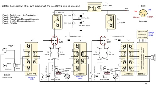
PARAFEED.
The two stages of this amplifier are Parafeed configuration. This is not strictly necessary for a Sakuma amplifier, but it I choose to do so for two good reasons, I will explain those here. All in all this design is nicely straight forward, and does immediately what we expect from it, without any surprises or difficulties.
The First reason for Parafeed: It splits the requirements for the SE transformer in two functions, that each device will do better. The Anode DC current is send into a choke, which has no other function than being a high impedance. The good thing is, it can be an unlinear (frequency dependant) impedance even. This doesn't matter. As long as the impedance is "high" that is all we want from it. Besides there is no signal path through the anode choke. So you see, quite a low requirement.
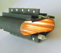
The actual signal path is another. The signal transformation (in this case, impedance transformation) is done by a so called PPZ transformer. Such a transformer is like a PP transformer, but it has zero air gap on purpose. "Zero" This is where the "Z" comes from. Here comes the other merit of a Parafeed design! Normally there is always some unbalance in Push Pull stages, never both tubes used, have identical bias. This can be 15%. So, a good PP transformer will always have a (small) air gap still. Since we really completely take the DC path via the anode choke, there is no small DC current through our PP transformer anymore. So we can go to zero air gap. In that way we will get much higher inductance, meaning the low frequency range gets significantly better. This may seem so simple to say. However, it means we can with the SAME performance, use a transformer of smaller dimensions, and this is exactly what GM70 needs. This is a transmitter tube, similar but larger and better than the 211 (VT4C) tube. Such tubes suffer from primary windings capacitance always. So the smaller the transformer, the lower the windings capacitance. And yes, with parafeed it can be made smaller! We have no DC component, forcing use to take a huge core, which would only make the copper wire longer, the windings larger diameter, and simply more windings capacitance. With PPZ we don't have this problem. So we can use the medium size transformer LL1679-PPZ for the output, and as inter stage we can conveniently use the almost fragile looking type LL1660-PPZ, though we use it on such a massive tube like GM70.
So to say it in other words, PPZ is specially made for parafeed applications. This PPZ signal transformer is now freed from the DC current, and will reward us s with very low distortion, and a much wider frequency range, when compared with the same transformer with air gap.
Moreover, voltage capability of a transformer increases very much when the air gap is removed, and in fact we are now using it at much lower saturation. Versus SE transformers which are always used close to saturation limits, as the DC current gives enormous pre-magnetisation to the core.
In a nutshell, the above is the advantage of parafeed. The disadvantage, if you want to say so, is the need for an additional Anode choke, but the cost of the choke, plus smaller PPZ transformer is even lower than the huge SE transformer we would have otherwise needed.
The second reason for using parafeed here, is to stay in line with the Sakuma principle. Now, we can elegantly duplicate the complete output stage without any change, and we use it as a driver stage. This is the principle, so drive a triode stage by a stage of similar construction. By this, we can be sure, the distortion behavior as identical to the end stage, but.... in anti-phase, so total distortion of the two whole amplifier will be low.
The total gain needed, is also produced by the input transformer and inter stage transformer, which produce gain as well, but at much lower distortion than a tube, and virtually noise free and virtually microphonics free. This works very satisfactory because of the low plate impedance of the GM70. Interesting, plate impedance at lower voltage becomes lower than normal for the GM70.
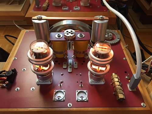
We all together, we use the Sakuma principle here, driving a GM70 with a GM70. This design is extensively tested and build as final version too. This amplifier produces a healthy 10 Watts per channel. The choice was not to go for highest possible power with small component count. So any of you who are satisfied with the output power of a 300B amplifiers, but looking for this sweet, silky sound of those high impedance thoriated Tungsten tubes.... here is a very nice amplifier with the GM70. Output power with 2x 10 Watt is higher as some 300B amplifiers, and the output power can be increased significantly and easily, without having to change the transformers. Even the mains transformer needs to to be changed. Only the capacitors must be adapted, for the higher voltages used. It is recommended to build it first as 2x 10 Watt amplifier.

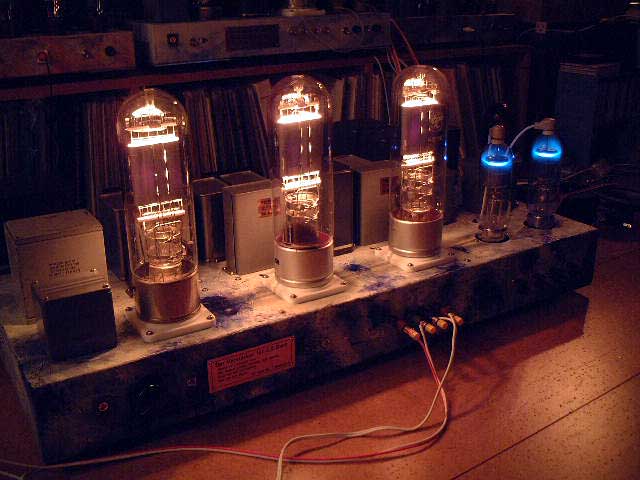
What you see here, is two mono blocks. So one GM70 is the output tube, the other is the driver tube.
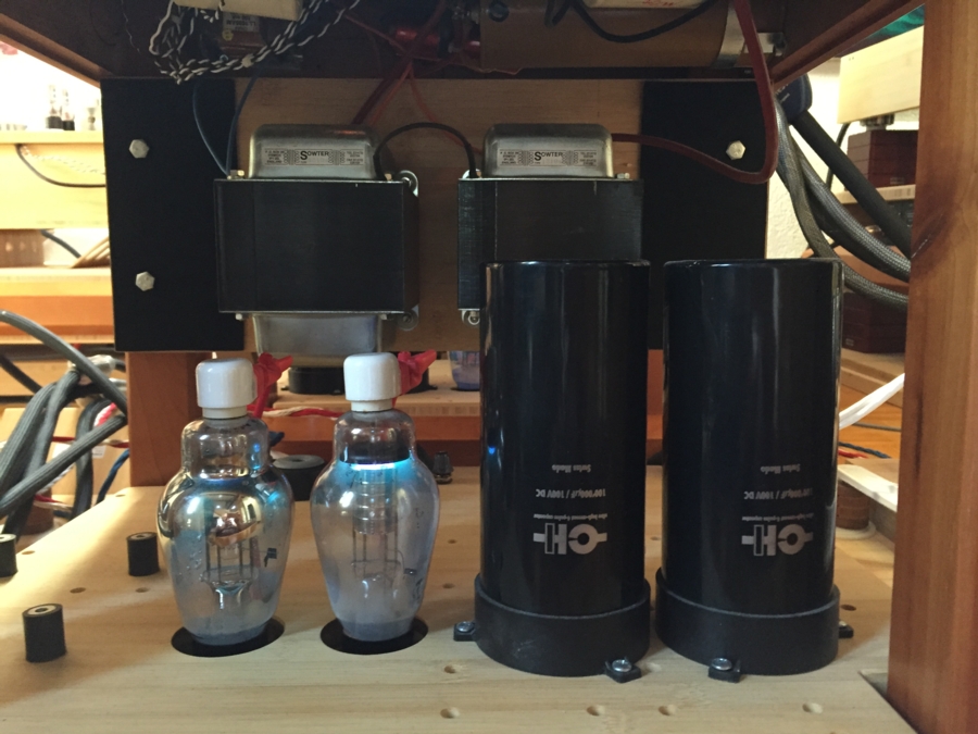
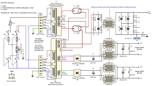
Power Supply with Mercury rectifiers
If you want to re-build this nice amplifier, please contact us. We give a some l discount on all amplifier kits like this. This is a very good working, tested design, but we have only for sale the main components. So not the resistors, and also not the mains transformer. For the rest, most other parts we have..
The power Supply
we are using mercury rectifiers in here. These light up beautiful, and also are very well suited for high voltage and high current at the same time. Actually producing a rectified almost 1kV with normal (Barium Coated) rectifiers is not really easy to do. Besides mercury rectifiers are virtually indestructible, vs. (Barium Coated) rectifiers are kind of sensitive and difficult to use at such high voltage and such high current at the same time, so we would end up with heavier types like Television booster diodes or similar. The choice was for those nice Mercury rectifiers. Such types like 866A can be found still as NOS, at reasonable prices, so when you like tube rolling, this is a good choice.
When using Mercury rectifiers, you need to know they need some special attention. Before applying high voltage to them, they need to be fully warmed up. Even though they seem to work "cold" as well, it's wrong to do, and it written so in their datasheet not to do this.
For warming them up, the easiest way is use a separate (small) transformer for their heaters only. Then, switching this transformer on the primary side is a convenient way to switch the heaters. Otherwise, using just one transformer, means you need a relay to switch 900 Volts DC, which is a very large and difficult relay. Or a solid state relay perhaps, but all in all this becomes a strange and not nice solution. Whereas a small transformer just for the 866 heaters is not expensive, and when we make this choice anyway, we can let the other heaters run on the same transformer also. Now we can even pre-heat the GM70's, which will reward you with better lifetime.
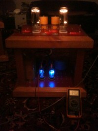
Un boxing NOS 866.
When you take NOS 866a out of the box, you will see there is not much Mercury inside, perhaps a little trace, but the glass is clean. That is because most Mercury is still in the capsule. Such capsules is just a small container with small holes in it, and inside is a drop of Mercury. It's the way to put in that drop of Mercury, without it getting lost, while welding the glass, etc. First time you switch the tube on, at first it's just a red glowing heater as any other. But then, slowly the glass will get all shady with gray stuff. This is normal. So don't worry, this is the Mercury now evaporating from the capsule as it gets hot, and the Mercury condenses at the cold glass. This is the phase where you should NOT switch on the high voltage yet. Though pretty obvious, if you ask me, it is happily forgotten by many, and it can cause shorts or tube damage. Then, after a few minutes, the glass begins to warm up, and the Mercury that was on the glass, will now evaporate, and the glass becomes clean. This (and not before) is the moment you have a gas-filled tube, and you can switch on the high voltage transformer. Now the burn-in your the new rectifier begins. After an hours or so, it is in maximum condition. Some are at maximum immediately, which is not better, just another way they are made.
For switching OFF the amplifier, you can do something nice for your GM70, to enlarge their lifetime. First you switch off the high voltage. After that the GM70 will cool down even though the heater is still running, it will become less hot without anode voltage. Then after that you switch off the heater as well, and the amp is switched off. This will keep the GM70 longer in good condition. Though lifetime of GM70 is exceptionally good anyway, this is always better for any tube.
Next time you switch on the amplifier, the 866a will again develop the shady glass, and you just wait a few minutes until it is gone, and then you can switch on the high voltage. Note, that eventually the glass of the 866 will become a little bit unclean. It's not really dirty, but it's not completely clean anymore. This is normal with Mercury rectifiers, as the Mercury will transport residual dirt that is inside the tube, to the glass. When the Mercury evaporates the dirt will stay on the glass, which is a much better place for that, than on any other (active) part of the tube. All in all, Mercury rectifiers are more reliable, and last a LOT longer than high vacuum diodes.
Here comes one disadvantage: They get into conductive state with a negative resistance curve. This results in relatively sharp switching on, when you use very large first capacitors, and it's the reason for disappointing results when designers are not aware of this. This can create some higher order noise hum. So, no dark sounding 50 (or 60) Hz, but higher order products like 100Hz, 150Hz, 200Hz. etc. To prevent this, the first capacitor is chosen quite small. The power supply is more regarded like an L-C power supply, as the C-L-C which you might expect at a first glance.
To prevent any hum, we have used a great option of the Lundahl transformers, as these all have a double coil. The power supply output is completely inductively separated from the rest of the circuit. If you look at the power supply schematic, you see this blue dotted line. There is no direct copper wire connection from the outputs to the rectifier tubes, you always need to pass an inductor. So there is no way out for the hum signal of the rectifiers. The power supply becomes dead-quiet.
About the Choice of the GM70 tube.
The GM70 tube is a transmitter tube by the datasheet. However, similar transmitter tubes like 211 and 845, are recommended by RCA and GE for Audio purposes officially in their datasheets. This can be done with the GM70 also, and result is actually a lot better as with 211 or 845. The reason why (profit oriented) HiFi industry has never jumped on the GM70 is because by definition, tubes is not what they can make money with easily. If an 845 amplifier gets sold for 8000 Euro, and materials costs is 2000 Euro, the profit is a factor 4x. However, this becomes impossible for them, when NOS 211 tubes are used, which cost 300 Euro one. In case of a Push Pull amplifier, four such tubes must be purchased for 1200 Euro. The whole amplifier would cost 4800 Euro additional, and nobody would buy it. However, four 211 tubes directly from the Chinese factory costs only 100 Euro for the four together. So their choice is simple and obvious. WIth GM70, the problem is the same. HiFi manufacturers would have no other choice as to buy from NOS tube dealers, because the Chinese don't offer such a tube cheap from new production. However, there is supply of GM70 from Russia, not really cheap, but also not really expensive. Still, the usual profit factor of 4x cannot be achieved by them, and many take simply 211 and 845 instead. So companies offering commercially build GM70 amplifiers will be not many, and this will always be so. As long as you understand how this bubble of opinions around the sound of 211 and 845 amplifiers is working, each can decide for himself what he wants.
Some points unsorted.
- A reason why professional manufacturers do not like GM70, is the relatively high heater power of this tube. Though this is the merit of GM70, and the reason why it works so well on medium anode voltage already, the problem is still this increase the cost of the power supply. For which cost increase, they get no return of extra output power. Yet, customers always ask: What is the output power... what is the output power.... And if the output power of an 845 amplifier is specified at a true and honest 10 Watt, buyers will not even bother to look at it. So if you are looking for best ratio of output power versus cost, you will end up with 211 and 845. Still, for real HiFi, GM70 is a the much better tube choice. I will explain in the following text.
- Tubes like 211 and 845 are rated at 20 Watt output, but this is only before the transformer, and is only above 1300 Volts anode to heater. (So above 1400 Volts in Auto Bias) and it is a matter of taste if you regard the distortion level above 17 Watt has something to do with HiFi. Moreover in Class A, they are by the datasheet not recommended at 100 Watt anode dissipation, but this would be needed to enforce the output power. So there are sharp contradictions here, ending up with "so called" 20 Watt amplifiers, by very high name vendors, effectively running on 1100 Volts only, and can give 20 Watt only at high distortion. At low distortion level as needed you get only 14 Watt or so from the tube, and the transformer looses 2 Watt internally. They are burning down the Chinese tubes at 100 Watt dissipation, whereas even RCA says that is not a good idea. But to get the power out, they have no other choice. So users have to exchange tubes sometimes every 2000 hours because of this, and before the 2000 hours are over, there will be r problems like crack sounds or hum, which is blamed on the tubes. (Instead of blame on bad amplifier design)
- Tubes like GM70 are much different. First of all, the very high heater power makes is possible to use the GM70 at relatively moderate voltage. We work at 920 Volts and still get 10 Watts out one channel. There is no other such tube which can do so. GM70 unique with this.
- GM70 is not at all used in this design at maximum anode dissipation. We all know, that using a power tube at full maximum dissipation is frankly quite a bad idea if you have something in mind like reliability. So we use this 140 Watt tube at 90 Watt here.
- This amplifier can be remarkably easily modified for higher anode voltage, and output power will rise to approximately 20 Watt. Yet the maximum dissipation of 140 Watt for the GM70 will not be reached.
VOLTAGE and Output power
The relatively small value of the first capacitor, allows you to adjust the effective output voltage within remarkably wide range. This amplifier was made for 920Volts, but with an unregulated power supply this will always be difficult to achieve precisely. First thing, we have to say here, it must not be precisely 920 Volts, as the amplifier bias is adjustable anyway. Yet we have a very wide adaption range of the working voltage by simply changing the value of the first rectifier capacitors.
The power supply can be raised later to approximately 1150Volts, by only increasing the first capacitor that comes after the 866 rectifiers. If done so, the parafeed coupling capacitors must be changed to higher working voltages, and also the chassis wiring carrying the higher voltage should be rated accordingly. This will enable an estimated 20 Watts per channel with remarkable little modifications in general. This option is unsupported and untested, but should be possible.
Specifications
Input impedance: |
4200 Ohms |
Output impedance: |
8Ohms or 16Ohms |
Frequency range: |
12Hz ... 30kHz @ 3dB |
Output power: |
10 Watt per channel at 920 Volts power supply |
Increased output power: |
20 Watt per channel, at 1150 Volts power supply, see text. Unsupported and untested |
Finally
This is amplifier works predictable and reliable. There are no strange tricks or things that nobody understands. The Sakuma principle at first does not have to be understood even. Believe me, it works also if you don't understand it :) It is just extremely satisfying to adjust this amplifier for best sound, by choosing the working point of the driver stage such, that you will see on an oscilloscope, how distortion disappears, or find this point by hearing tests.
DISCLAIMER
Please understand we have to say the following for legal reasons, but we do have to say it. Otherwise we get held responsible for errors of people want to build a HIGH VOLTAGE tube amplifier while learning by doing, and do not realize that trial can result also in error, with dangerous situations. So we say this clearly up front here: This is only a report here, about this (wonderful!) project, and for legal reasons we claim this is NOT to be an instruction about how to do this safely on our responsibility. So if you decide to re-build this project, we sure help you out with questions and issues if there are any, but whatever you do, you should have full understanding yourself of risk and safety related to it. All actions are 100% on your own responsibility. So when we write "you have to do this, and you must do that" this is only the way the text is written, but the text below is intended only as a personal report only. I hope you understand why we say this.
CLICK HERE TO JUMP TO THE BUILDING INSTRUCTIONS
GM70 mono block circuit diagram


Parts List
Includes most items, but not small resistors, fuses, etc
Revisions List
Revisions were very few so far.
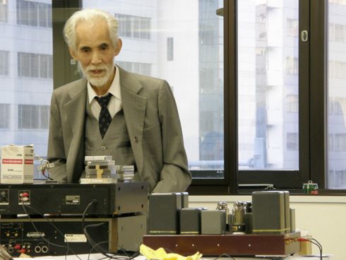
The picture you see here, is by Philippe M. from Switzerland.
 |
|---|
Left mono block |
SOME SIMILAR PROJECTS FROM JAPAN
Mono block with 4212 tubes, and Mercury rectifiers.