Electron Engine ™
Printed Circuit Boards by Emissionlabs
Cutting the ground loop with HiFi amplifiers
We explain this here, as an example with the Yamamoto A08-S amplifier, using the EE31 board
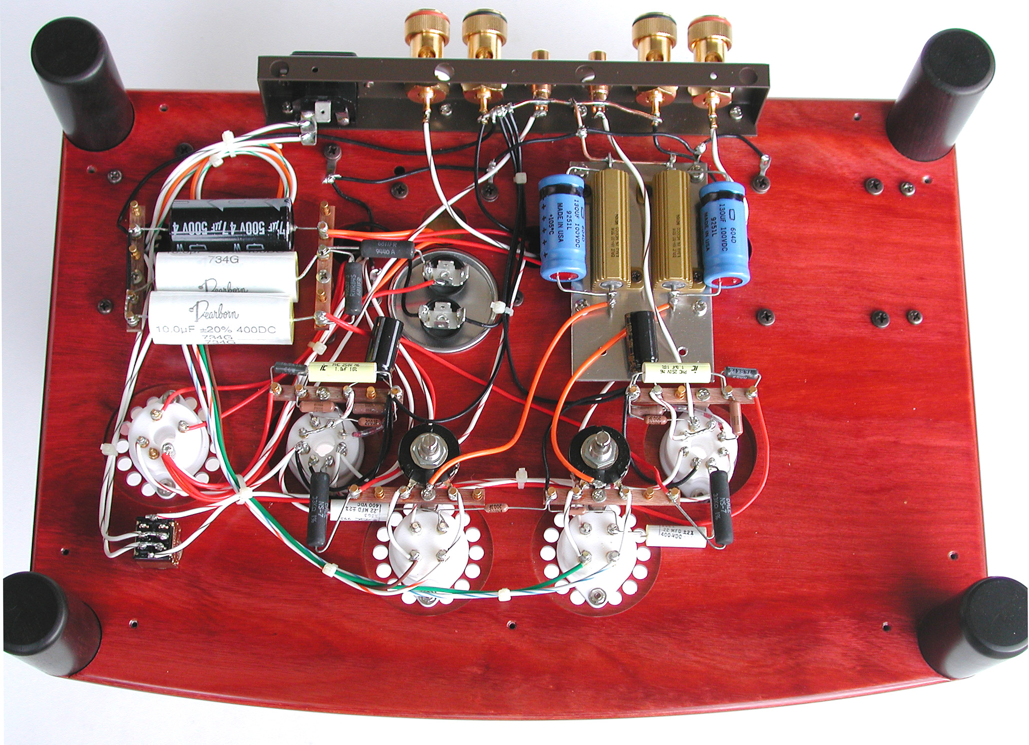
Click here for a large picture
Cut the Ground Loop.
Hum is the most difficult thing to solve, because signals are too low to be measured. It can be caused by several factors, and it is not always possible to say, what exactly has to be done, and what exactly it will achieve. But most of the time, a ground loop is the cause, when difference products are attached to each other with standard RCA connectors. That is because the wire for the tone signal is also the shield of the cable. While this shield also connects the metal chassis to each other, and by this inter act with the mains ground. How and why exact this may cause hum is not easy to explain, but we call it: Break the ground loop.
Such a ground loop can not always be physically pointed at. A ground loop is created by definition, when two pieces of equipment are grounded via the mains, and also their ground is externally connected via the shield of the tone cable. That is indeed a physical loop. Such a loop technically is one winding of a transformer. Any magnetic stray field from mains transformers, will also stray into this loop, and if that happens, a small signal will be generated, because that's what transformers do. You may think, it is only one winding, but it is a very large winding, several meters in length. What counts actually, is the loop surface, but that is quite large as well. Unfortunately the tone cable shield is part of this loop, and the hum signal will be injected in it. Understanding it like this, it will be clear, better shielding, or ultimate RCA connectors will not cure this. The only cure is: Break this ground loop, so no current can flow in it, and the hum will be gone.
With an asymmetric, standard RCA connector, the signal is between center pin and ground. So when you have music signal on the center pin, and a hum signal on the ground connection of the RCA, you will hear both. Cutting the ground loop, in this case means: Disconnect the ground of the RCA cable from the chassis. In order to pick up the signal still, we use a transformer winding as the input, and this winding will not be grounded. (Floating). Now, the ground loop is cut, and we still have signal at the input of the transformer. The output is then grounded normally, and the amplifier input sees no difference.
How to mount the EE31 board.
 The principle for the this tweak is, to keep the original RCA connector of the Yamamoto, since it has already a floating ground type. So to say, we are almost done. We only need to re-wire it for the EE31 Board. If the connector in your amplifier has no floating ground, you need to replace it.
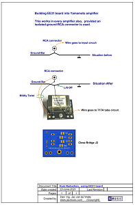
- For the Yamamoto, with a soldering iron, lift off the ground bar from the RCA input jack, but leave the ground wire undamaged and as it is, for the rest of it.
- Both terminals of the RCA jack are first disconnected, and it should be checked with an ohms meter vs. ground, if this is really so. Unplug the audio input cable for this!
- What is left now is only the center wire, which went to the RCA connector. Take it from here, connect the EE31 board, and it already works.
- For this, connect it like in the drawing. At the back side of the board are jumpers, configure for 1:1 by closing the according Jumper. Leave "Gnd" Jumper open. Solder the green drop capacitor, and an 8k2 resistor on the board (Or 10k if you have no 8k2 around)
- Since we mount the EE31 Board in the Yamamoto amplifier, most likely on a wooden part of the chassis, we have no chassis ground. For this reason, the Jumper Gnd can be left open. The Ground connection is now made, by connecting ''Out-'' to the ground bar, at the place where we lifter it off the RCA connector. So THREE wires go to the RCA connector (indeed!) and these have the same function as the three wires of an XLR connector. This method works elegant and mechanically easy. Mildly drill the two wires In+ and In-. Do not drill the ground wire with this.
- Configuration 1:2 is not advised in the first place, but can be tried later. This gives extra gain.
- You will see, this works quick, easy, and very good.
How to connect this with cables?
Actually there is little to know or do. There are two cases.
- If the pre amplifier has RCA connectors, just use any standard RCA cable.
- If the pre amplifier has XLR connectors, a special cable has to be made, once side XLR, one side RCA. The XLR cable is connected the normal way. The RCA connector is connected with the center pin to XLR2 and the RCA ground to XLR3. The cable ground (XLR1) is only connected at the XLR side.