Electron Engine ™
Printed Circuit Boards by Emissionlabs ®
EE21 Multi Purpose Board V6.4
 Overview (you are here)
- MC Applications
- Amplifier Input Applications
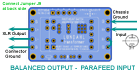
- Amplifier Output Applications
Introduction
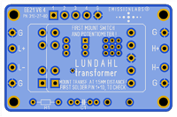 Finally, no more glueing transformers inside the amplifier! Our customers had sometimes hum issues which are hard to solve, because precise measurements below 1mV are impossible with 50Hz mains voltage everywhere. For this reason, using the right concept from the beginning is the only good way. Not, wire it by hand, and then tweak hum away by trial and error. This can really be tricky. Like power supply diodes have large peak current in Ampere range, which causes their leads to radiate a magnetic hum field. This field can generate only very small voltage in near by wiring. Yet when this finds it's way into pre-amplifier wiring, all things becomes very strange. Even so, when experiments show a contradiction, this characterise such a problem, but that holds little clue to the true error. it's just a trial and error game, and you are on your own with the problem. Hum is a always compatibility issue. So at the position where hum is generated, make the source smaller, and where hum is received, make this place less sensitive. This is the golden rule. For this reason, from Version 6.3 or higher, the board has now a ground plane, so there is virtually nothing which can go wrong with unintended (hidden) ground loops.
After designing this small PCB, I was surprized how many transformers can be used with it. Gain, Attenuation, Phase splitting, Phase reversal, balanced to unbalanced or vice versa, using a termination network, use an external gain switch.... ALL if this is possible. Do not try to understand all applications together, and understand all the connections and things that have to do with it. Simply read only what applies for intended application, and then for the transformer of your choice, and connect it with the advised connection schema. Like this the right choice is made very quick, and you can't go wrong when building it.
The EE21 board works before having to worry about jumpers or termination, which comes all afterward. As a minimum only the gain has to be set with the jumpers (J4,J5,J6) for the Option1 board. Boards with Option 2 or 3 will not even need this, and work straight away after the cables are connected. For this, simply use the Connection Schemes overview (see contents above here).
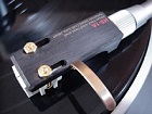 Moving Coil. The EE21 board is made to work simple, and yet can do many options which you may want to play with later.
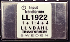 Input Applications. A totally different application as Moving Coil. Yet the pin lay out of these transformers are the same. So it was logical to make a combined board.
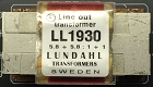 Output Applications. These are typically tube parafeed applications, apart from LL5402 which is very low impedance, and intended to drive it with transistors or an IC. Choose the gain, connect input and output, and the board works.
 Connections. The functionality can be changed very much, by the way the board is connected.
Gain Setting
Actual gain or attenuation depends on the application (so the transformer chosen).
Each transformer allows two gain factors, and two additional factors for types which can be used reversed. The two gain factors can be chosen fixed with solder jumpers, or variable using the Piano switch.
The gain can also be selected externally, when using the External Switch Board. This optional board can also be added later.
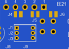 Gain Option1 Solder Jumpers |
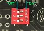 Gain Option2 DIP Switch |
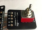 Gain Option3 External Switch |
| Choose Gain
with J4, J5, J6 |
Choose Gain without solder iron. |
Choose Gain externally. |
After choosing the gain (High or Low), the board basically already works.
About the Versions
6.4 is the latest version. Release Dec 2020.
Version 6.3