Electron Engine ™
Printed Circuit Boards by Emissionlabs ®
EE21 Board, Input Applications
- Overview
- MC Applications
 Input Applications (you are here)
- Output Applications
- All Connection Schemes, Complete Overview
- Unsorted Application Information
Part1. Create Balanced Inputs, with or without gain.
There are input transformers intended for gain, some for and 1:1. Some have high impedance, some have medium impedance, and then there is the core material to choose from. There is great overlap with the applications, this is basically what it comes down to.
| Input | Low Gain |
High Gain |
Core |
Characteristic |
| LL1588 | 1x |
2x |
Mu Metal |
Neutral sound. Can be reversed for 1x or 0.5x Gain. (So 2x attennuation). Will not damage from DC component if it happens. |
| LL1592 | 1x |
2x |
Mu Metal |
Neutral sound, High Signal. .Can be reversed for 1x or 0.5x Gain. (So 2x attennuation). Will not damage from DC component if it happens. |
| LL1690 | 1x |
2x |
Amorphous Cobalt |
Best Sound of Amorphous. |
| LL1674 | 4x |
8x |
Amorphous Cobalt |
Medium Impedance. Can also do 1:2 but not with the EE21 board. Can be reversed. |
| LL1676 | 2x |
4x |
Amorphous Cobalt |
High Impedance. Can be reversed. |
| LL1948 | 1x |
2x |
Amorphous Cobalt |
Best Sound of Amorphous, 6N 'Cardas' wire. |
| LL1922 | 4x |
8x |
Mu Metal |
Neutral sound. Will not damage from DC component if it happens. |
| LL1930 | 5.8x |
11.6x |
Mu Metal |
Designed for parafeed pre-amplifier output. Will not damage from DC component if it happens. |
| LL5402 | 1x |
2x |
Very low impedance output |
Reading all data sheets is only confusing. Better is, from the ABOVE, make the preliminary choice of the transformer, and then final choice becomes easy. For instance for a high impedance input, there is LL1676 or LL1588. Do you want amorphous core? If so, LL1676 is the answer. For mu-metall, the answer is LL1592.
- Application with LL1588
- Application with LL1922
- Application with LL1674, LL1676
- Application with LL1592
Inverted or None-inverted signal?
An amplifier should not invert the signal, but amplifier manufacturer pay little attention to this, because when it "works", they say the product is good. However an inverting amplifier can cause instability problems if there cabling errors. Yet because nobody cares, so this is random, and in 50% of the cases, an amplifier inverts the signal. Which is simply wrong to do. In such a case, if an inout transformer is used anyway, CHECK if the amplifier perhaps inverts the signal. If so, phase reversal at the transformer can elegantly correct this. More information about this.
Creating an BALANCED input
I recommend this as a standard for tube amplifiers, but using the RCA (Cinch) input for this. Like this you are compatible normally with all existing equipment, using the RCA (Cinch) connector, but you get the advantage of a hum-free, balanced input. More information about this. For this, an isolated ground type RCA (Cinch) connector has to be used, such as the Yamamoto.
Hint: When connecting a balanced RCA (Cinch) connector, even an XLR connector can be connected in parallel to it.
Fake XLR inputs
I do not like to say it, but many amplifiers (with great brand names!) have fake XLR inputs. It is clear why they do this, because a real (balanced) XLR signalling is costs them a transformer, or additional electronic circuitry. There is no other way. And people know XLR is professional, and it makes them happy to see those professional inouts. So what will the fakers do? The buy a 1$ XLR connector from China, and internally dump the XLR-3 signal in a resistor. So the signal is only used from the XLR-2 line of the balanced pair. If you buy it, you think you get XLR? Well yes, the XLR connector only. Electrically it is a fake. So people pay the extry price to have for instance a pre amplifier with XLR outputs, and connect it to the (fake) XLR input of the speaker amplifier, and think is better. This a fraud to my opinion, but regard it please my opinion only. The situation is however, suuch an amplifier has already the visible part of the hardware at the outside. So specially here, using the EE21 board for instance with LL1588 or LL1676 in 1:1 configuration is the BEST you can do. Even so you can save some money, and use the EE31 board too, which is very basic and it does what it needs to do.
Hint: When the EE21 board is used, and connected 'balanced', an RCA (Cinch) and XLR can be connected in parallel. For this, an isolated ground type RCA (Cinch) connector has to be used, such as the Yamamoto.
Part2. Termination Network
When an RC termination network is mentioned the Lundahl datasheets, begin with just using this, and it will work very good to begin with. Some data sheets do not specify such a termination, but when we read the data sheet carefully, and it can be seen, a load of for instance 10k Ohms was used achieve the result. Now this is normal, because without any load at all, any tone transformer will self-resonate at some high frequency. In HiFi there is no requirement for very high impedance inputs. Only historically speaking, the old 47k requirement for RIAA amplifiers is still a good value, and it is a de facto standard. For other signal inputs it is definitely NOT a fixed 47k. You may as well say 10k or 47k, and actually with that suit the transformer better. And this is what Lundahl does.
Important is: We MUST load some transformers by a minimum load of 10k. Then everybody is happy, and when the pre-amp which it gets connected to, has 50k to 100k, that doesn't matter.
when the transformers have no electrical error in the audible range. Above 20kHz, at some point some roll of begins. This comes in earlier if unsymmetrical used.
A termination network will make most transformers linear up to a higher frequency. Some types perform best with an RC network as load. Some other typed need only a resistor, and some need no termination at all. For this reason, a variable resistor allows just try it out, and also switch the damping on and off with Solder Jumper J10, to hear the effect. More information here.
Transformer |
Gain |
Termination |
Jumpers |
1x |
Variable network: R1=2k2, P1=50k Adjust for best square wave response at 5kHz |
J1+J3, or J4+J6 And J10. |
|
1x |
Fixed network R1=10k |
J1+J3, or J4+J6 And J8 + J10. |
|
0.5x |
Variable network: R1=2k2, P1=50k Adjust for best square wave response at 5kHz |
J2 or J5 And J10. |
|
0.5x |
Fixed network R1=10k |
J2 or J5 And J8 + J10. |
|
8x |
Variable network: R1=10k, P1=250k Adjust for best square wave response at 5kHz |
J1+J3, or J4+J6 And J10. |
|
8x |
Fixed network R1=47k |
J1+J3, or J4+J6 And J8 + J10. |
|
4x |
Variable network: R1=10k, P1=250k Adjust for best square wave response at 5kHz |
J2 or J5 And J10. |
|
4x |
Fixed network R1=47k |
J2 or J5 And J8 + J10. |
|
| Best square wave response is done with the intended load, connected to the outputs H+ and H-. If unknown, use a 47k resistor for this. Specially with a gain of 8x this is important. In some cases, the external load of 47 may be the right one to take by coincidence, and the network may be switched off by opening J10. | |||
 The network is universal for all transformers. This means only some parts of the network are used, depending on the application, or perhaps even the network is not used at all.
Here is the recommendation how to do this the best way. First the board needs to be tested for basic function. For this reason, I recommend to solder the transformer into the PCB first with short wire pieces of 3cm. Like wire pieces you cut off from resistors. This is easy to remove later, and otherwise once the transformer is soldered on the board, it will be difficult to remove. You can de-solder the small wires from it, but it is not specified for desoldering from a PCB. This may push in, or pull out the pins, and the internal contact breaks off. For desoldering, I use a solder bath, so I can remove it free of force. That works very good, but as said, this is not specified officially.
For the adjustment procedure, first disable the network, by opening Jumper J10. In this condition, the best gain factor of the board has to be found first. For easy reference, the High signal inputs have the letter 'H'. The board should not respond with hum, when touching the transformer metal. Experiment with the two gain factors. Basically it must work absolutely free of problems, and 100% as expected. If not, find the reason for this first, before final mounting. The solder islands of the boards are very good quality and will not damage easily be a few times soldering.
When it works all good, and the best sounding gain is chosen, the best termination network has to be found. If a network is needed at all, because some applications like parafeed work without it.
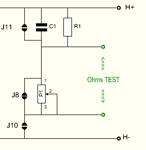
Optional: Some people do not like a variable resistor in the sound path, and it can be replaced by a fixed resistor. In that case, the variable resistor is shorted, while leaving it in for later experiments. However to find out it's best value, the variable resistor has to be used. The way to do this, is as follows:
- It is assumed the board is good working, and P1 is adjusted, either for best square wave response, or for best sound with some test music.
- Open Jumper J10. In this condition, an ohms meter can be connected to the 'TEST' points.
- Do not measure across the test points, with J10 closed, because the DC Test current (1mA) from the ohms meter may damage the transformer.
- Now the value of P1 is measured.
- Replace R1 by a resistor, which equals P1 + R1, and close Jumper J8
- Verify if the "TEST" points have zero ohms now, and Close Jumper J10
1) Application with LL1588
This is the neutral transformer, giving a gain of 1x or 0.5x. Yet by reversing the board, a gain of 2x can be achieved also. So buying the EE21 with 1588 gives three options.
In case you have chosen LL1588 for a 1:1 application, and you find out after all, some GAIN would have been better, here is an unspecified use, but it will work, and give a gain of 2x. Close only Jumper J2, and leave all other jumpers open. Now REVERSE the EE21 board, like below, and you will have a gain of 2x. I have not tested this, but I see no reason why it will not work. More information here.
2) Application with LL1922
This is transformer for creating gain of 4x or 8x.
A transformer creates gain free of any noise and hum, and a distortion level better than any tube. Also if a driver stage has 'almost' the required gain, do not add another tube stage, and get stuck with too much gain and noise. Just add a step up transformer!
The drawback of a step up transformer is it's relatively low input impedance, in the range of a few kOhms. Yet, today we do not have the 1940's requirement any more where an amplifier had to be 47k in order to be an optimized load for a crystal record player. (Yes that's where the 47k came from, long ago). So when the source can easily drive 2k, which is today totally normal, why not use a step up transformer, and get noise free gain + a balanced input?!
Termination Network
A termination network is not mentioned in most Lundahl datasheets, when the transformers have no electrical error in the audible range. Above 20kHz, at some point some roll of begins. This comes in earlier if unsymmetrical used.
A termination network will make most transformers linear up to a higher frequency. Some types perform best with an RC network as load. Some other typed need only a resistor, and some need no termination at all. For this reason, a variable resistor allows just try it out, and also switch the damping on and off with Solder Jumper J10, to hear the effect. More information here.
3) Application with LL1674 and LL1676
These are two very classical Lundahl transformers for impedance matching, or a 1:1 47k input with the LL1976. Used by many. Both have a core of amorphous iron.
Basically LL1974 is medium impedance, and LL1976 is high impedance, but here again the EE21 board offers some additional variations.
Gain |
Termination | Jumpers | ||
Single Output, impedance matching No Parts mounted. |
4x |
600 Ohms in, 10k Out. (Can be reversed) | J1 + J3, or J4 + J5 |
|
Phase Splitter Output No Parts mounted. |
4x |
Source must be 150 Ohms | J2, J3, J6 |
|
High Impedance (47k) input No Variable Resistor mounted. |
1x |
R1=33k | J1, J3, J5, J7, J8 |
|
High Impedance (47k) input |
1x |
R1=4k7, R2=100k, adjust R2 for best square wave response | J1, J3, J7, J8 |
|
Medium Impedance (10k) input No Variable Resistor mounted. |
2x |
R1=68k | J2, J5, J7, J8 |
|
Medium Impedance (10k) input |
2x |
R1=10k, R2=220k, adjust R2 for best square wave response | J2, J7, J8 |
|
| J1,J2,J3 Set Gain. J8 connects Termination. J5 shorts R2. J7 Shorts C1 | ||||
4) Application with LL1592
This transformer will go up to 100kHz with the RC network for tuning. The EE21 Board has this option
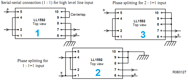
From the above datasheet (screens shot)
Serial 1:1 connection:
Solder Jumpers J2, J5, J8.
The variable resistor is not needed, but if mounted, it can be left in.
R1 and C1 are the termination network, by the datasheet. 7k and 400pF.
Connect G to Ground
Inputs: L+, L-
Outputs H+, H-
Phase Splitting for 2: 1+1 input:
Solder Jumpers J2, J5, J6 J8.
The variable resistor is not needed, but if mounted, it can be left in.
R1 and C1 are the termination network, by the datasheet. 7k and 400pF.
Connect G to Ground
Inputs: L+, L-
Outputs H+, H-
Phase Splitting for 1: 1+1 input:
Solder Jumpers J1, J3, J5, J6 J8.
The variable resistor is not needed, but if mounted, it can be left in.
R1 and C1 are the termination network, by the datasheet. 7k and 400pF.
Connect G to Ground
Inputs: L+, L-
Outputs H+, H-
Fine tuning:
In case you want to fine-tune the termination network with an oscilloscope, a variable resistor can be used of appr 15k. It has to be attached to the board before soldering in the transformer! Open Jumper J5. R1 becomes 1k, but it's value is uncritical. The functioning of such a termination network depends greatly on the RC-Time. This is why the capacitor can be a fixed value, and the resistor can be variable.
Phase splitter output


XLR Input with LL1588, LL1922, LL1674 or LL1676

RCA (Cinch) Input with LL1588, LL1592, LL1922, LL1674 or LL1676 . Using Isolated Ground connector