© COPYRIGHT NOTICE All Rights Reserved
![]()
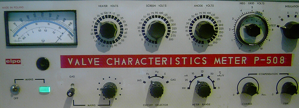
ELPO P508 Tube tester
(Last updated:
06-Jan-2023 16:05
)
I have started this report in April 2016, but I have so little time. It can take quite a while before I have this tester running nicely.
This is the one I bought
![]() Ebay, here we go again. According to this (!%"$) seller on Ebay Germany, it was very accurate, but it produced only large errors when I tried it. Many Ebay sellers have this attitude, they first try to fool you, and when you find out, they offer generously to take it back, and expect this makes the buyer happy. I say, what's the use, when I have all the mess here, with packing and unpacking, and doing the testing for nothing, and even have to pay shipment myself. So I still decided to keep it, give him a negative, and repair it myself.
Ebay, here we go again. According to this (!%"$) seller on Ebay Germany, it was very accurate, but it produced only large errors when I tried it. Many Ebay sellers have this attitude, they first try to fool you, and when you find out, they offer generously to take it back, and expect this makes the buyer happy. I say, what's the use, when I have all the mess here, with packing and unpacking, and doing the testing for nothing, and even have to pay shipment myself. So I still decided to keep it, give him a negative, and repair it myself.
The defect is with "meter range range" switch, that seems sure. When I measure for instance "20mA" on the 100mA range, and just set the knob to the 25mA range, I get a totally different result. As this part of the tester (the meter) works the same as a normal analog multi meter, I thought it probably had some broken resistors inside, and I initially thought such problems are can be fixed easily. But, having learned from the past, I have little illusions, and I prepared myself for the usual situation: Dirty repairs, by quite clever people, doing only what is necessary to get make it work, no matter how much additional damage this does , and then quickly dump it on Ebay. That kind of work. Indeed, that was just how it was. The problem was not the resistors, but the switches themself. They have a big problem with the axis, and totally messy and inadequate fixed it with glue, and yet is worked for the moment, and that only done to selling the tester quickly. What happens after that, when these heavy switches break the off the glue soon, was fully unimportant for this friendly German seller with his perfect 100% feedback profile. (not any more). Typical Ebay. And typical for those extremely smooth sellers. So this friendly older German gentleman got a well deserved, negative feedback from me. I don't want to mention the person's name here, but from his phone call I would say he is from the year 1950 or so, and he does the "business" together with his son. He knows a lot about the ELPO, and he says he can repair them. He has schematics and spare parts and everything. Not many of those people are around like that. So, when you find an auction from an extremely knowledgeable elder gentleman in Germany.... I whish you good luck. The rest is about the ELPO P508 itself.
The ELPO P508 is unusual. It is Polish made, in the glorious days of the Socialistic worker's paradise. So they had access to Russian military products, and it seems obvious, the sockets are the same (excellent!) parts, same as used in the Kalibr L1 and L3 testers. The test settings interestingly seem copied from the AVO manual, but edited and Russian tubes added to it. They managed to buy the famous AVO roller switch too, from the United Kingdom, where the evil capitalism ruled. Well, sometimes you should not be so critical :). Even so, they used the AVO Principle in detail. The ELPO P508 seems to me like an AVO Mark 5 for that reason. From the way it is operated, it reminds me so much of the AVO tube testers. I have not studied the schematic in great detail, bit it seems to have some sort of oscillator, and then we talk about the AVO CT163 even. So somehow, this tester seems very promising to me. As a meter, the same surprize: It uses a tout band meter, with the brand name "ERA" on it, this is a still existing Polish company, dating back to 1926. Here is a link to their website. They still sell analog panel meters. Similar meters I have seen from the East German company MTM Mellenbach, but a Polish reader told me, these ERA panel meters are their own production, not MTM. A tout band meter is friction-free which is very nice. So when they get older they stay good. Furthermore they're more resistant against mechanical shocks, and overload.
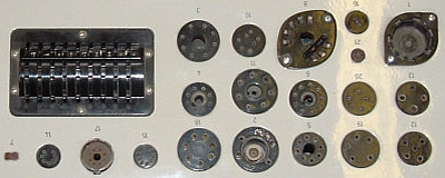 |
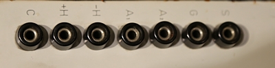
Tube sockets. The are the same as on the Russian KALIBR L3-3. Though I find it a bit dangeous, as the sockets Nr 2 and Nr 8 have their contacts sticking out, with up 450V Volts on it. Best is probably to stick an old, empty tube base in socket #8, and detach the contacts of socket #2 as that one is only for military tubes anyway. Selector. It does have the nice AVO selector switch on the top, so company connections to this AVO clearly must exist. (Who can help me to find this out???). |
|---|---|
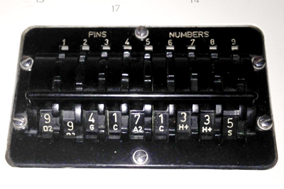 |
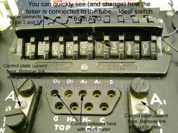
Selector. It does have the original AVO selector switch on the top, so company relations to the AVO Company have existed. (Who can help me to find this out???). Moreover I hope to be able to take settings just from the AVO handbook. That is the most complete data directory I know, but it is of course related to this AVO switch only. That would be nice when the book works for the ELPO as well. Just to explain this switch quickly, if for instance pin #9 is connected to the screen grid (S) the last digit of the "connections" number is 5. You can see this in the picture on the left. If the cathode is connected to tube pin #4, the fourth digit is a number 1. (Also as in the picture). For not connected tube pins, there is a "0". Remark: Unlike all AVOs I have ever seen, this switch runs smooth and light. I can't say anything about this now, but it gives me good hope for my old AVO testers again. |
|
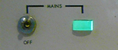
Mains Adjustment switch. This is combined from resistors and transformer taps, i have to study why that was done. The switch itself is bad quality, but with my P508 it is ok still. In case it gets broken, replacement is simple. The switches is a standard 11 positions 30° type, and these cost only 10 Euro on Ebay from old supply. |
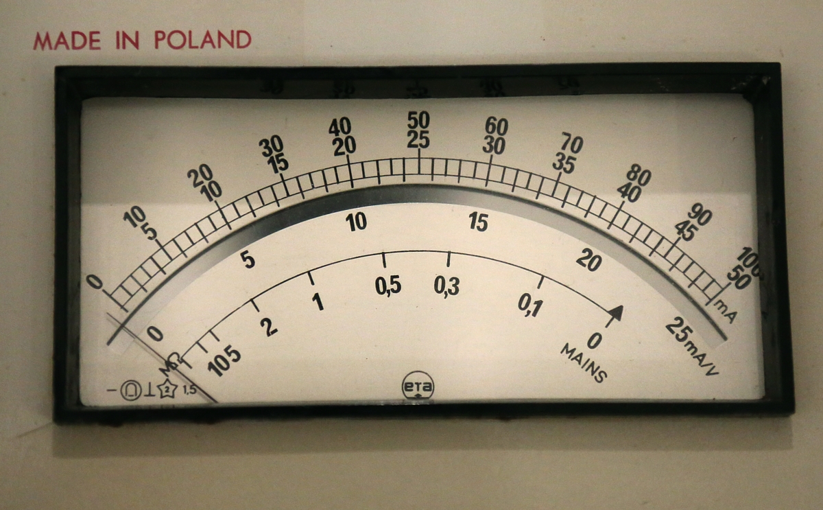 |
Meter. It uses a tout band meter with a brand name "ERA" on it, but to me it looks like a meter from the East German company MTM Mellenbach. A tout band meter is friction-free which is very nice. So when they get older you don't get a stick-slip effect. Furthermore they're more resistant against mechanical shocks and violent overload, banging the needle in the corner. So if the meter is the more rugged, that is a good thing. Also the more sophisticated overload circuit of the P508 will have it's function here. I think the classical "broken meter" problem as we know from the AVO's will be much less of a problem here. |
 |
Insulation test. It has the usual shorts test system of the AVO. Which uses a special designed switch, it shorts all tube electrodes, apart from one. Which one that is, can be selected. So when you set it for cathode, all electrodes are shorted, apart from the cathode, thus being one connection. The other connection is the cathode, and simply resistance is measured. So not just you get an indication for a short, but also for leakage. If there would be a short between grid 1 and cathode, the meter would show a low resistance at "G1" and "C". So you know the resistance of the short, and between what electrodes. Negative Grid volts. Same method as in AVO Mk3. (Mk4 has a reduction gear on on it, Mk3 has a direct connection). The potmeter used, is fantastic quality. It looks rather like an auto transformer than a pot meter. In the middle os the course range, so 10...20...30...40....50V. Then outside scale adds 0....10V to it. That limits the grid voltage to -60V, which is not enough for large triodes such as 300B. However, they can be tested still if lower anode voltage of course, but in case you choose 400V, you are going to need 80...90 Volts in the grid, and this will not be possible. I am sure, this can be fixed with a small additional transformer. You would get an additional switch saying +50V. |
|
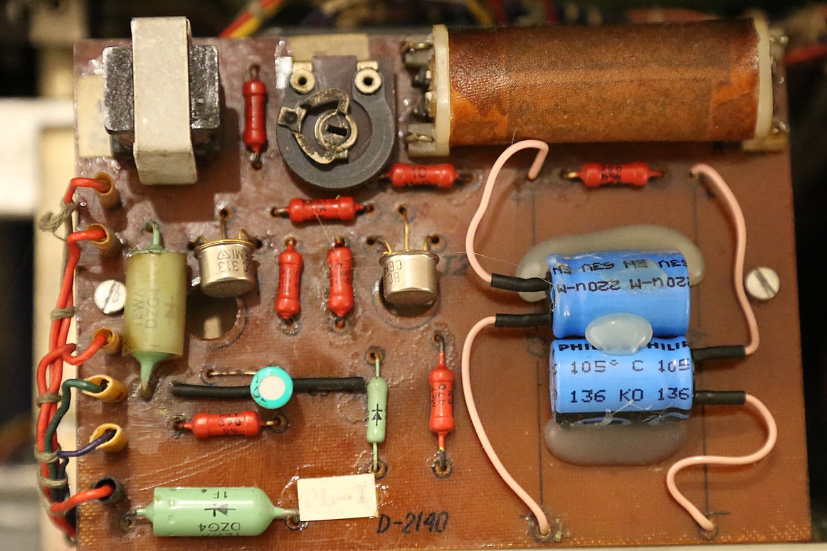
Overload Relay: Owners of the AVO, will know the overload protection is very inaccurate, and you cannot trust this to protect the delicate panel meter. I would say, with an AVO, that's not what it's for. It rather protects the transformer of the tester itself. In the P508 things look a lot better. It has a nice, very sensitive electronic circuit. On overload, it switches from a green light to a red light. The relay seems a reed relay to me, so very fast, which again switches a power relay, to make the tester inactive. I haven't checked the board yet, but somebody replaced three capacitors, and the transistors. The original transistors are mounted upside down, in the holes. To me it looks like the board was not working, and somebody just replaced all things that might perhaps be broken. I don't like the appearance of these PCB capacitors in there. I probably will put some axial types in there, when I can find them. Also the pot meter is totally turned clockwise. On the other hand, I found internet pictures from others, showing the pot meter in exactly the same position. So, I will see about this board later. Actually those gold plated transistors are very good, you can't have a "tin whisker" problem with those. |
 |
The circuit works quite logical. As the ELPO (and AVO) use a rectified wave, any DC plate current is still represented as an AC signal. Via transformer Tr3, this is coupled. The transistor T1 switched the Reed relay, which has two contacts in the coil. Contact A2 performs a hold function. Contact A1 switches the larger Relay B5, which puts the tester in the "hold" mode. So the red lamp burns, etc. The transistor T2 works opposite to T1. So when T1 is is on, T2 is off, and vice versa. This keeps the current consumption of the circuit constant. So the supply voltage of T1 will stay constant. Well this is what I think T2 is for. Schematic1 English Manual Many thanks to Cristian Jelescu for sending this. |
|
Low Voltage Switches. It seems to me the range switch, and function switch are low quality stuff. Besides these operate far too heavy, this is crazy. They are imprecise, and sometimes get stuck between two settings. Though at t he front panel they indicate nicely the correct settings, at the inside they do not, and they seem to short. Well the actual switches seem not difficult to buy, just standard multi deck switches. So I will (need) to replace them. |
|
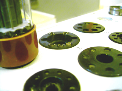
High Voltage Switches. The anode voltage and screen voltage switches are made from a PCB board kind of construction. I know this from some vintage multi meters. They seem good condition and well made. They operate smooth comfortable. This is definitely an improvement compared to AVO. Heater Voltage Switch. This is also the PCB kind of switch. I seems not right to me, switching tube heaters that can draw a few amps, with a PCB switch, but I have to say this switch is in very good condition. So it seems possible. |
Look at the picture quality. Done with a new Canon 5D Mk3.This was "automatic" mode. Can't change anything.
|
Connections to all electrodes are in the deck. That is convenient for service. As all tubes are all tested with half wave rectified AC signals, connecting a scope or a multi meter to those, is not going to tell you much about tube testing. Also the voltages probably apply to this funny AVO formula, with some 5...10% deviation for voltages and current. It was the AVO patent. Yet it allows direct control of what the grid pot meter, and anode voltage is doing. So instead of having to connect a multi meter internally somewhere, you can simply connect it here, for service. Furthermore, these banana connections are used for plate caps connections of course. |
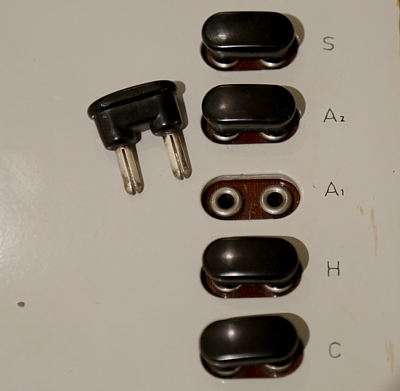 |
Those plugs are useful. You can insert a current meter in every electrode. When you set the meter to true RMS, all you need to do is multiply the value by two, to get the effective value you are measuring. You cannot use that to calibrate that, or do more precise measurements than the tester itself, as final calibration is for the whole tester as a unit. BUT... What fails is control grid current. I will sacrifice the Screen Grid current link for that, as screen grid current nobody needs to know very precise, and the panel meter can also show that . Whereas live viewing of Control grid current is much more important, and there is no way to measure this. So probably I just change that quickly myself, and put a small sticker over the "S" called "G1" |
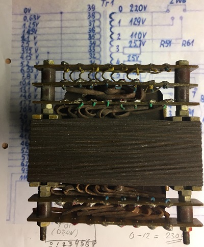 |
I have for sale this spare heater transformer. Look here for more details. |
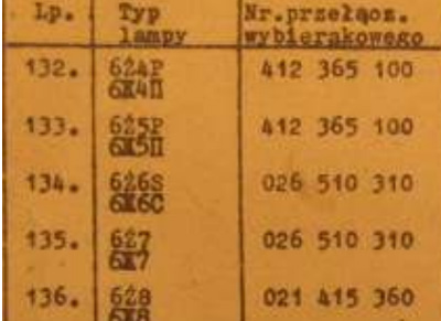 |
Due to 50 years of close friendship with Russia, this Polish tester had also many Russian tubes in it's manual. Most probably you can use the same settnings for an AVO. |

© COPYRIGHT NOTICE All Rights Reserved
![]()