Since 1993 Copyright Notice
How to Test Electron Tubes
Leakage test tool
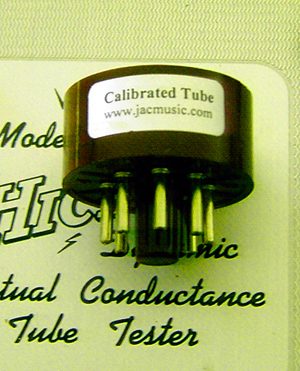
This is all we talk about... but it works so nice
This part is included with the calibration tube set, or can be ordered separately.
Definitions:
Leakage: This is a resistance between two terminals, of a kind that is unavoidable and accepted. This is a repeatable number, which is easy to measure. So this is always present, but it doesn't do anything bad, as long as limits are not exceeded. Often a leakage current is specified, like for instance 1uA Grid leakage.
Isolation: WIth isolation, we try not to accept leakage. Here, we want the best. Manufacturers to make resistance as high as they can, and specifications can also be like: 5kV isolation. Or, if the kilovolts are nor what we need, for instance 500 Mega Ohm, of 2 Giga Ohm, just to give some very high numbers.
There is also overlap. In many cases, you may as well specify the leakage, or Isolation. Both can tell us how 'good' the item is supposed to be.
Why a good tube tester must be able to test this CORRECTLY:
This is has known resistors inside. Your tube tester must identify these correctly as leakage or a short. If your tube tester fails, you need to fix this FIRST before you can trust any of it's results at all. Really you have a major problem with the tester, if a known 470k leakage resistor is indicated too low or too high, or can not even be detected at all. Also, your tester has to tell YOU where it found that resistor. Not the other way around. So if there is some resistance of 470k between Grid1 and Grid2, a good tester will tell you exactly this. All well made, historic testers are OF COURSE doing so. And no, there is no reason why modern testers should compromise on that.
There is no replacement for the good old neon lamp test, given the simplicity of the circuit, and how extremely reliable this works. Why this is not done with modern testers? Well this needs a complicated switch. Of the type you can not buy cheap. The answer is as simple as that. The automated testers would need some extra relays for this. Not very popular with the makers.
If your tester appears not even being capable of doing so, consider to buy a better one, or live with the compromise. Remember, heater to cathode leakage is the #1 cause of tube hum, while power tubes can self damage due to thermal drift, cause by leakage. So reasons for not having to test this, do not exist.
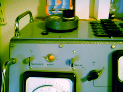
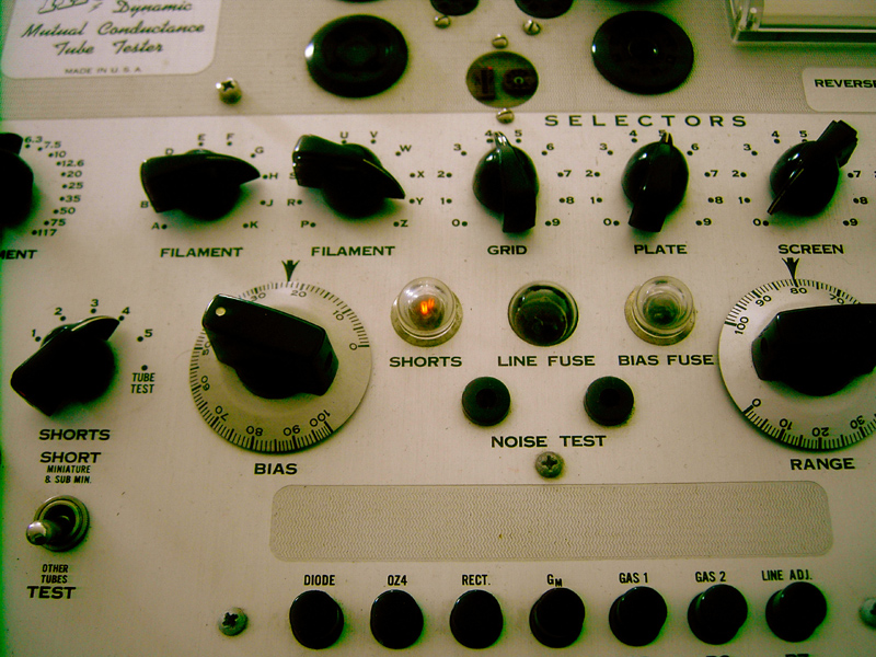
Some tube testers have a (limited) isolation tester inside. Some are state of the art, understanding the importance of it. The best is AVO, which measures directly in Mega Ohm, and it is many times more sensitive as you really need for tubes. The needle movement starts at 500 Mega Ohms, this is extremely sensitive. The Kalibr L3-3 has a tube nano ampere meter inside, and test voltages to choose from. It can indicate from mili Amperes to a few nano Amperes per division. The Hickoks have a neon lamp function for this, which can be calibrated from the inside, for 'just burning at the beginning of a problem'. It cannot be repeated enough how important it is, to have your tester all checked for correct leakage tests and isolation tests. If this part is ok, to begin with, this proves you have no leakage on the wiring or switches. With intelligent setting of the knobs, you can extract a lot of information, from the device under test.
When you order the calibration tube set, you receive this test tool with it. Your tester must be able to find the value of each three resistors, and also tell you at what pins they are.
- 2700 Ohms - simulates a short circuit
- 270.000 Ohms - simulates small leakage. (from cathode to filament, 400k is the limit for a good tube)
- 470.000 Ohms simulates very small leakage, but it should pass. Neon lamp must be off.
The interesting part is, depending on the settings of the tester (like choose 6L6, or 6SN7) the resistors will appear on other electrodes of the tube that is chosen. So for 6L6 for instance the 270k resistor will appear between grid 1 and grid 2, but for 6SN7 it will appear between plate and grid. So by choosing 6L6 or 6SN7 (and just let the adapter in the Octal socket) you do a different test. Each time your tester must give the right answer.
Important note: With the leakage adapter in, test only for leakage. That means, do NOT test for transconductance, or anything else, or you will damage the adapter and the tester too. Actually that is the same situation is with a leaky tube, it can also damage your tester. In old literature, this step is called: Pre-testing. So before you blow up a good tester with a faulty tube, the tester can detect such a tube during the pre-testing.
What to do if leakage is not expected? Answer: It depends if your tester BY DESIGN is capable of detecting leaks and shortage at all. If yes, the leaks and shortage in this test tool simulate two 'bad' values and one 'just ok'. It is just this, your tester should be able to tell. If not, it is a low class product by design, or it is defective otherwise.
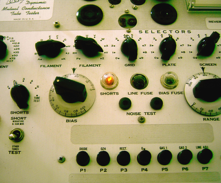
Many Hickoks have a potentiometer inside, which you can very conveniently use to re-adjust leakage sensitivity. This circuit works near-perfect, if calibrated well. The neon lamp has two plates (can be various shaped, but Neon lamps have always two plates). Adjust the pot meter such that the neon lamp JUST burns with both plates of the lamp. So first it burns on one plate, then adjust brightness until suddenly the second plate burns also. Now the tester is calibrated correctly. This included some leakage over the wiring and sockets, the tester may have, which is compensated and 'calibrated away' so to say. So the result is now, at 270k inside a tube, you will see this lamp status as you adjusted it, which is both plates just burning, very dim. At higher resistance as 270k, comes a moment where one plate burns, and somewhere around 400k the lamp will be off completely. Now remove the adapter and the lamp must be off. If the lamp still burns, you have socket leakage, which is out of range. So you see..... VERY important to know this, and many testers need a re-adjust. So you see it is just a little neon lamp, but if calibrated inside the tester, it is a very very good way to detect leakage, because it is tested with high voltage. You can't replace that with an Ohms meter. Also, you have a direct 'Good/ Bad' result.
In case you don't want to adjust from the inside: At least you know if the tester is doing this part of the test well, or not. Mind you that a tester that can test leakage, but will not find the leakage resistors in the test adapter, needs a repair before you continue using it.
Test nr: |
Settings |
What will the tester see? |
What must the tester say about this? |
Notes: |
1 |
Set tester for 6L6 insert adapter then do leakage test by the book |
2700 Ohms between heater and cathode. This is a practical value for a short circuit. |
Full short circuit. A tube like this is very bad. Your tester must definitely say so. Example with AVO Mk4 |
Leakage between filament and cathode happens very often, and gives hum, crack noise, and other problems. Even bias offset can result from it, causing the tube to burn down. Your tester should find the 2700 Ohms resistor at these electrodes here in test#1, which is close to a short circuit. So in test#1 we only check if the tester see this (yes or no). Also you will see maximum lamp brightness. So you know now, how that looks. Then in test #2 we check if your tester can find a 270.000 Ohms resistor, which value represents a beginning problem of cathode to filament leakage. So if your tester passes test #1and test #2 it will find cathode to filament leakage correctly. |
2 |
Set tester for 6L6 insert adapter then do leakage test by the book |
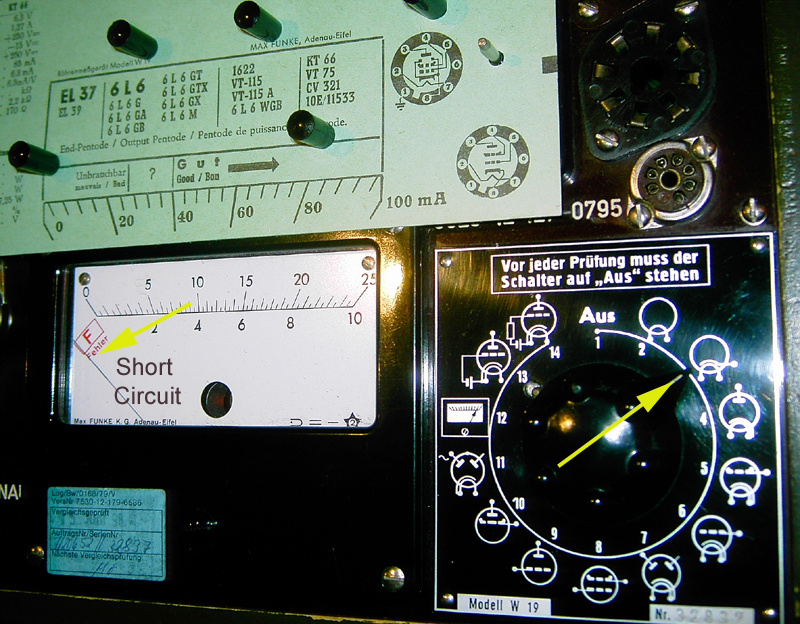
270k between 1st. and 2nd. Grid |
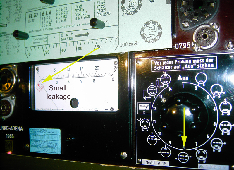
Small but dangerous leakage. A tube like this is very bad. Your tester must definitely say so. Example with Funke W19 The photo camera makes the difference look smaller than with the human eye. The 'dim' lamp is really very dim and the 'bright' lamp very bright. |
This leakage is unlikely to happen. We use this test only so you can see how your tube tester reacts to something we call 'small leakage'. Lamp will burn very dim, not flicker. A Meter type tester, will move the meter very little. |
3 |
Set tester for 6SN7 insert adapter then do leakage test by the book |
470k between grid and cathode of one tube half. |
Very small, but acceptable leakage. Test must be passed. Neon lamp must be off. |
The leakage is only on one tube half. Find out what tube half this is, according to your tube tester. NOTE: 270k is used since Jan 2010, for new test adapters. Earlier versions had another resistor value in here. |
4 |
Set tester for 6SN7 insert adapter then do leakage test by the book |
270k between plate and grid of one triode. |
Small but dangerous leakage. A tube like this is very bad. Your tester must definitely not accept this tube, while doing a leakage test. Lamp will burn very dim, meter type of tester will move the meter very little.
|
The leakage is only on one tube half. Find out what tube half this is, according to your tube tester. Find out what tube half this is, according to your tube tester. Plate to grid leakage is rare, but it can happen. The result is pop noise, or sputtering noise. In this test, we check if your tube tester can find this leakage, and at the same time we check if it registers the value of 270.000 Ohm as a 'beginning problem' All tube testers use the same detector circuit, regardless what electrode is tested. With neon lamp testers, there is often an adjustment potentiometer inside. If the neon lamp will flicker on and off, the tester is not sensitive enough. Flickering may happen at 400k, but at t 270k it must burn dim and steady. |
MORE DETAILED TEST FOR THE AVO ONLY
AVO is the king with this, and it works fast as well. Any other good tester is able to come up with the same results, just it is presented in another way. The easiest is with Funke W19 and Hickok. With AVO, Funke and HIckok, within 3 seconds you know everything.
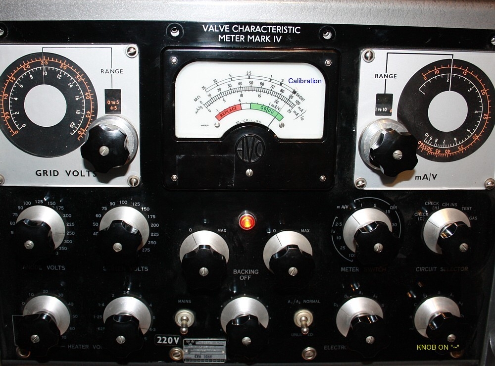
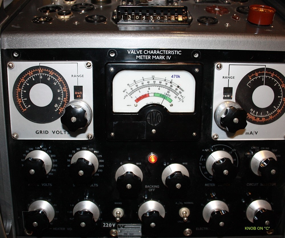
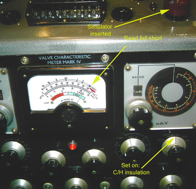
TEST1. We all know this one. It's the mains calibration. For all these tests, the circuit selector must be on CHECK(H). As you should know, if any of the tests that follow now, give a reading on the meter, you have a faulty tube. A faulty tube means: Do not set the circuit selector on 'TEST' as you will damage the leakage test tool or the tester, just as with a real broken tube. We verify here the function of the isolation test. Isolation means something is close to non-conductive, but shows some leakage under high voltage. So leakage and isolation is something else. In tubes, a small leakage for instance from heater to cathode is fully normal, when the tube is at maximum dissipation. Objects like wiring and tube sockets from the inside, but also the tube mica, etc, must have good isolation. For this reason the AVO works at a double wave rectified DC voltage, with a peak value of 116 Volts. The 9Volts of a hand hold multi meter, is too low voltage, and besides such tools often cannot measure above 20 Meg ohms anyway. So here, your AVO is a true isolation tester. It works at higher voltage. Beginning of the needle movement is at 500 Meg Ohms, and the first calibrated scale line is at 25 Meg Ohms. Then with the Isolation knob, on the bottom right, and setting the socket connections with the dial wheel, you get an immediate result in Meg Ohms for each tube electrode. So if you measure 1Meg with the switch on 'G', the grid has an isolation error of 1 Meg Ohms. This is extremely convenient, you detect any isolation errors for the whole tube, immediately, and the result in Meg Ohms. I must say, that specially for this extremely convenient measurement, I keep a fully calibrated AVO Mk4 here. I even use it to measure isolation of other devices, like transformers, by just connect two wires to a tube socket. This is hard to replace by anything else. The nice part is, the current is limited at 27uA, and you can hardly damage anything with 27uA. Not even a semiconductor. So it would be nice to know if this test has any problems. Use the leakage test tool for this, as in the following four pictures: |
|---|
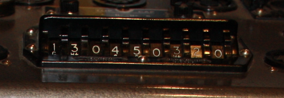
Now set the dial wheel for 130450320 and insert the TEST TOOL in the Octal socket. |
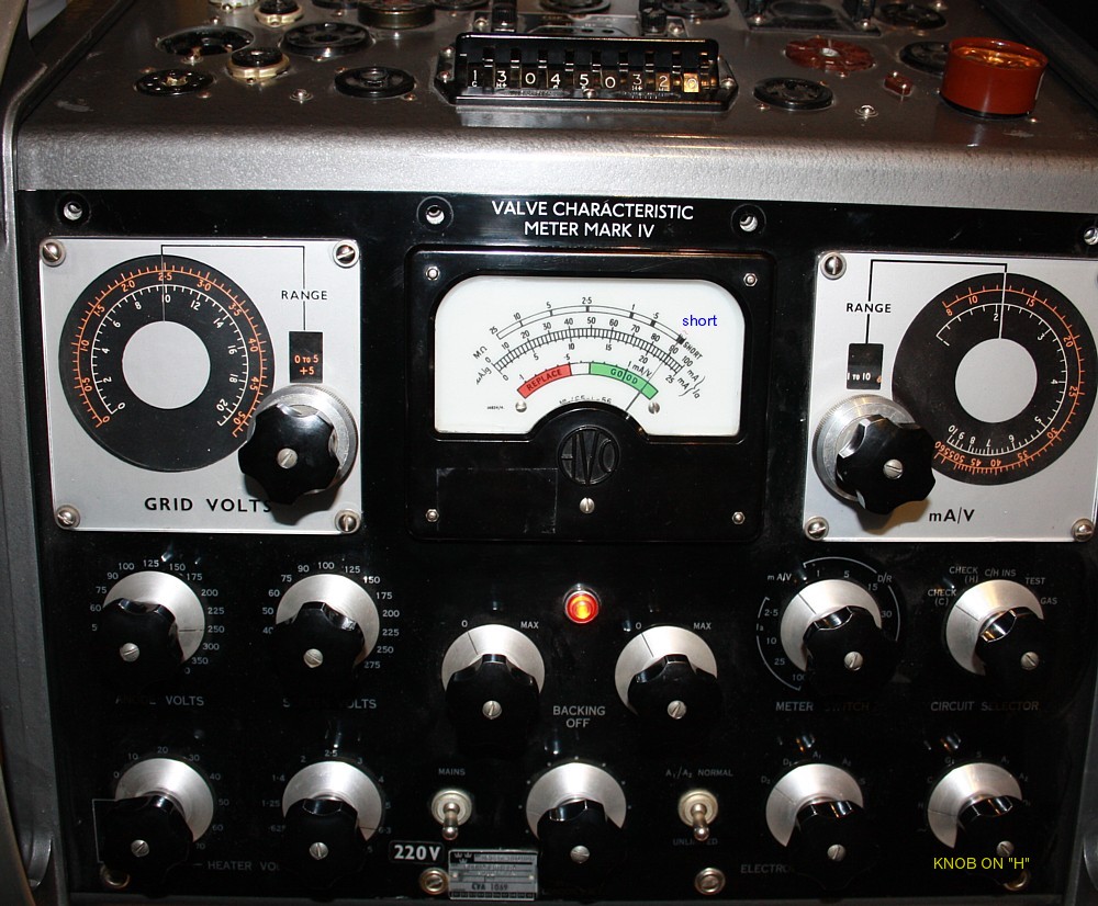
This is the heater test. The knob is now on H. We have connected the 'short circuit' resistor of 2700 Ohms here in the heater connections of the virtual tube that we have on the dial wheels. So the meter must indicate a 'short', meaning the heater is ok. |
This value of 470k is chosen with care. The limit, for a non leaky cathode-to-heater is 400k. So this value of 470k is simulating a 'just good' tube. Some tubes can give several Meg Ohms, but 400k or better, is 100% good. The test here is, your AVO must indicate 470k, as on the above picture. |
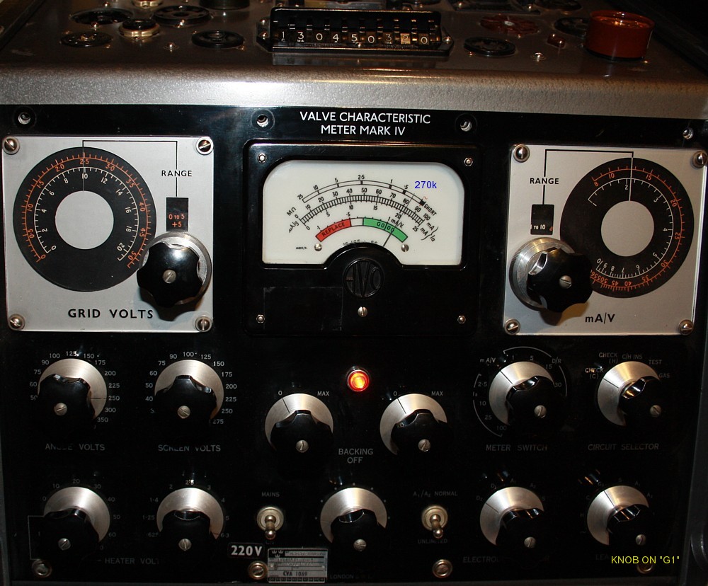
This is another test. The knob is now on G1. We have selected with the dial wheels the resistor of 270k between G1 and S (S for Screen). So on 'G1' and 'S' you must measure 270k. |
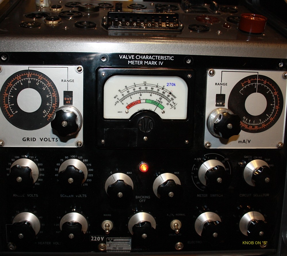
This is another test. The knob is now on S. We have selected with the dial wheels the resistor of 270k between G1 and S (S for Screen). So on 'S' you must measure 270k as well. The test here is, you must have the SAME READING as in G1. If there is any very small difference, you have some internal leakage on one of the sockets of the tester. This can be a drop of coffee spilled inside a socket, or contact spray inside, or some remains of glue or wrong lubrication substances. Since these resistances are in parallel, a small move such as 2mm of the needle, when going from G1 to S, means you have appr 200 Meg Ohms, somewhere at the inside. |
FINAL TEST (no pictures)Remove the leakage adapter, and now in any of the positions you must read almost 'zero'. I would say 0,5% of full scale is just ok, but not more. So that is 0,5mA on the 100mA scale. This represents a few hundred Meg Ohms for the internal wiring and switches. Conclusion: Did it all pass, that is excellent for you. If not, the things to do are beyond the scope of this page, but roughly it means,check the following: 1) meter sensitivity 27uA full scale. 2) Correct reading at 25% and 75% too. 3) Check the series resistors for the meter, these are the two that are the 'matched pair', and are together 2,96 Megs in series. It must be at 0.5% ! That needs a very precise ohms meter. They are found on the circuit selector switch. (Check service manual). 4) Check if the fuse is at a position that corresponds with the actual mains voltage, and check if the mains calibration switch acts accordingly. So if the fuse is at 230-250V and you have 230V, it means the calibration switch should be almost at the last position clockwise. And no other position, or you have another error somewhere. |