You are here at Analog Testers, Part1, AVO Testers
General part about AVO tube testers
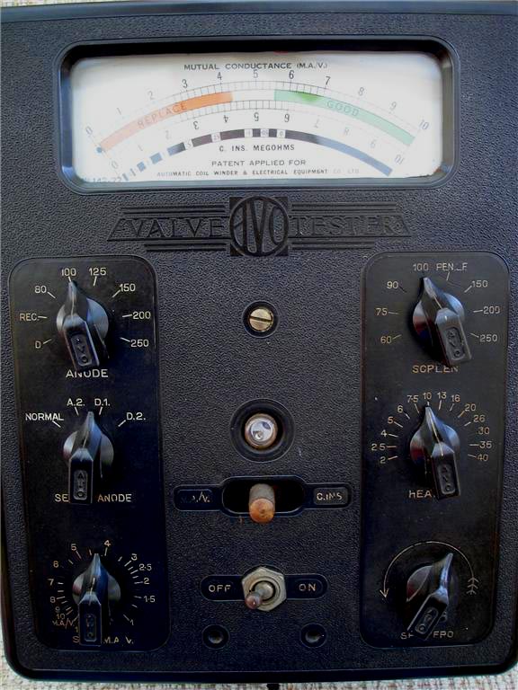
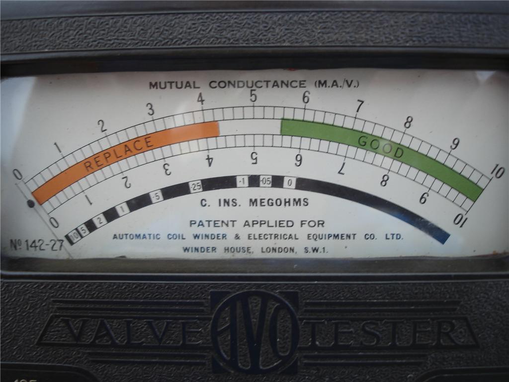
Calibration
Help! My tester seems uncalibrated! For calibration, the manuals say you need to measure the Anode and Screen voltages with an AVO8 meter. This meter gives some load to the circuit, and the voltage drop is included in the test values, as AVO writes. Though I have to say, that voltage drop, I can not see it. It is much different with the grid voltage. That has to be measured with a tube voltmeter, or today with a very high impedance electronic voltmeter. So not with the AVO8. More important is, any modern meter, do t NOT use the more expensive RMS meters, but the cheaper, so called MEAN VALUE meters. RMS and Mean Value do not differ when we have a sine wave, but sine waves for the mains voltage is history. Today, the waveshape is heavily distorted, so when we talk about calibration, and measurement errors we do not want, we have to stay in line with the AVO patent, saying this works based upon average value. I prefer my good old AVO 8 for this, just taking no risk and doing things the right way. It was however quite an effort to find a good AVO8 meter. They are much sought after, and mainly crap is sold on Ebay. I had to send them all back. I noticed, most people bid very high on the latest models, but these are not the best! These have laser trimmed resistors, which was nice in those days, but they had not re-painted those after trimming. So the burn marks have now deteriorated and their values have changed. So you buy a mess almost by default. Moreover you can't take those newer ones apart as there are solderable foil PCB's in there, which are almost impossible to re-solder. So I got hold of the last model with untrimmed resistors (Welwyn panclimatic precision resistors) and normal wires instead of foil, and it was 100% good, the way I bought it. More information here. Precision of the AVO testersI do not have all numbers, but the plain, good old 1930 Valve Tester is very high precision, it's amazing. Provided it is good, and you do not buy somebody else's scrap and unrepairable mess. Data of Mk1 and Mk2 I do not have. Mk3 and Mk4 work the same, and should have the same accuracy. In the Mk4 manual I found this:
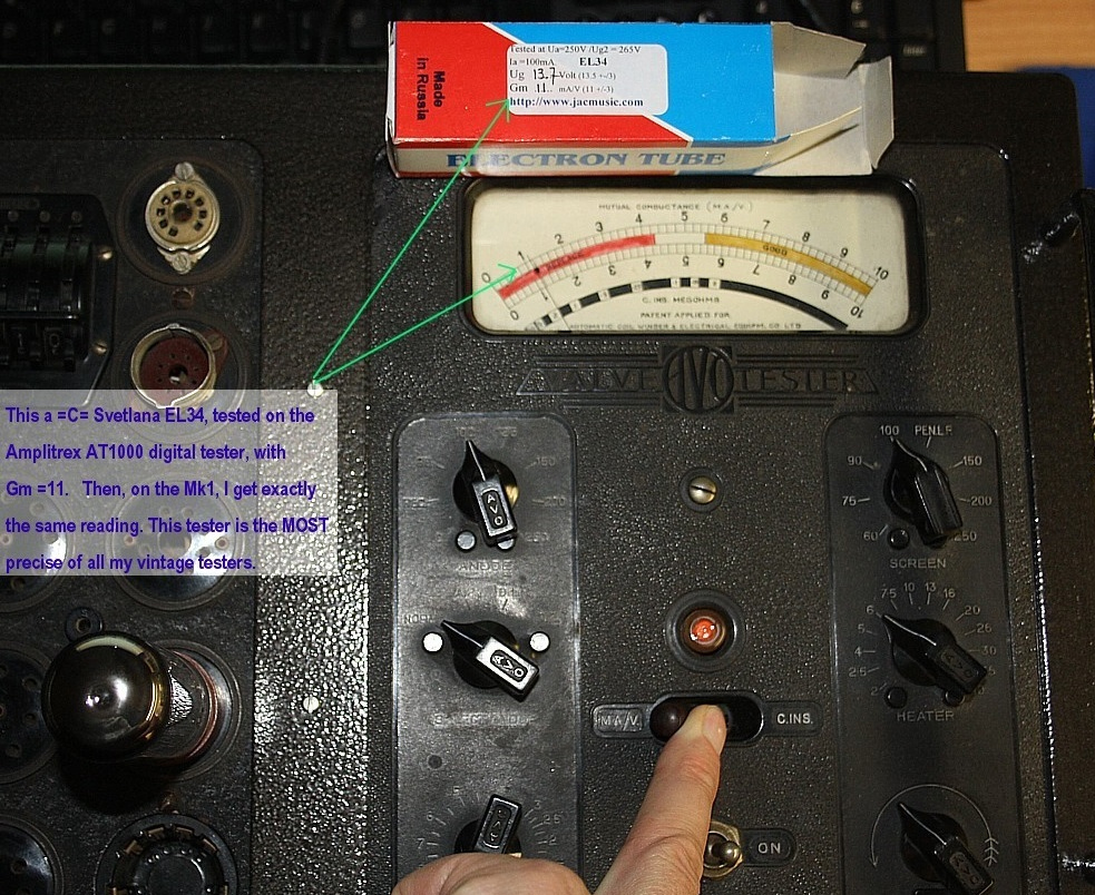
Given that anode current error is a composite error, 10% is very good. It adds up from small errors with all things that we need to use, like : Anode Voltage, Control Grid, Screen grid, Heater voltage, and panel meter error (Which I know is max 1.5%). Still ending up with 10% only, is a real achievement, and many Mk4 are not at the maximum limit of 10% but do a lot better. What is outstanding, the Transconduction measurement error of only +/-5%, this is where most modern testers fail in a terrible way, when testing low current tubes. Such tubes like ECC83 must be tested at only 1.2mA. You may as well call that 1200uA. So at digital steps of 0.1mA, which is hard enough already, that alone is 8% error. So comparing a well calibrated AVO Mk4, with any expensive digital tester, and you see a difference? Well, the smaller the tube is, the more you can expect, the AVO is the winner. Reason for this outstanding accuracy, is the "backing off" system of such a measurement. Since we "zero" the meter before doing a transconductance test, we get in ONE step the result. Whereas all digital meters make two steps, thus doubling their own error. Which error is large already, with tubes like ECC83. It's hard to beat an AVO with this. Very hard. Only such testers which work with a test tone, will do better, because then again we have only a single measurement.
The Mk1/Mk2 has a very high range of specifications. These are:
Mk2 Electrically this is face lift version of the Mk1, but there is little difference. Ease of useBoth Mk1/Mk2 are more convenient to use, and to service than Mk3/Mk4. What speaks in advantage of Mk3/Mk4, is slightly more precision with larger size tubes, though this difference is small, and you may not notice it. What is nice, is the rugged case of Mk3/Mk4, and sure the lovely looks. Still I think performance / Price ratio of Mk1/Mk2 is a lot better. With Mk1/Mk2, after backing off, you can switch back and forth between Plate Current and Gm, simply by a switch. Folks... this was SO WELL DONE. With Mk3/Mk4, this comfort is gone. In case you want to flip from Plate Current, to Gm reading, this is NOT possible without doing backing off every time. Which I find extremely annoying. Also the backing off with Mk1/Mk2, is done with one knob only, and is fully stabile. The Mk3/Mk4 uses two knobs, and still that works not always good. So think well, with some of the special features of Mk3/Mk4, what exactly these are, and if you are really in need for this, and if that is worth to you the more difficult operation and higher price.
Also left out (VERY unfortunately) is the lamp backlighting of the previous models. It was real backlighting, so through the whole meter, the scale is transparent, and from behind is a window. This was simply beautifully done with Mk1/Mk2, Mk3, and i love it. Besides, there is the red 'fault' lamp of the Mk3 was also left away, because the Mk4 meter is not transparent anymore. This was really impressive when you make an error with the older Mk3, and the tester goes into fault mode. The power is switched off, the tester buzzes at you, and a 25Watt red lamp burns from behind the meter very bright. Mk4 has only the buzzer and power off. The diode rectifiers and Selenium Rectifier, were replaced by silicon rectifiers in the Mk4, which may seem an advantage, but in reality the silicon diodes of the Mk4 can damage, and the diodes of the Mk3 will survive some foolishness. In favor of the Mk4 is they moved the service panel from the bottom to the left side panel. This is really an major improvement. Also there is some theoretical improvement in test results, as the Mk4 has works with a half sine wave testing the tubes, whereas Mk4 puts a full sine wave on the anode and G2. This should make no difference, as during reversal of the signal (so negative anode voltage) the tube will cut off anyway. The Mk4 system is a bit more elegant, but as said, I found Mk4 not work better because if that. Without the meter back lighting , and more difficult way to read Vg and Gm number inside a peep hole, as in the Mk4, I prefer myself actually the Mk3 above M4k! Though most people see that different, and Mk4 prices are a factor 1.5 or 2 higher.
|
|||||||


 With a two panel valve tester some repairs are really difficult, like a fault in the flip switch in the middle. However that seems rare. Some other repairs are easy, such as a loose meter glass, loose wires, bad contacts. Many small issues which are just only service. Overall, when you are good at electronics, and prepared to learn how this item works, you can always repair it. But do not expect to start without any knowledge, and fix quickly on a Sunday afternoon that nasty problem, which two owners before you have failed to understand the cause. Also the Gm pot meter may be defective. I think you can always repair it, as long as you have the skills. When you don't have the patience, a broken pot meter is a killer factor, because it is an integrated part of the deck plate, and it has strange scale.
 Very Early Version, without Noval Socket. These testers have a Mk1 and Mk2 version, and I do not know the exact differences. When you have one like pictured here, it's a M1k for sure, but it is possible some other versions of the Mk1 existed as well. My impression is, the Mk2 is a version with more transformers, buy really exactly I do not know this. Very Early Version, without Noval Socket. These testers have a Mk1 and Mk2 version, and I do not know the exact differences. When you have one like pictured here, it's a M1k for sure, but it is possible some other versions of the Mk1 existed as well. My impression is, the Mk2 is a version with more transformers, buy really exactly I do not know this. |
 It is difficult to see if this one already has a noval socket. For sure you need to check that when you buy one. It is difficult to see if this one already has a noval socket. For sure you need to check that when you buy one. |
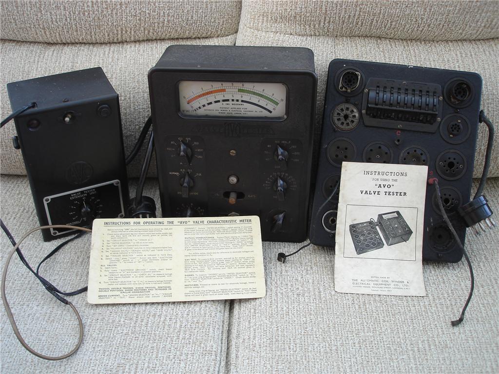
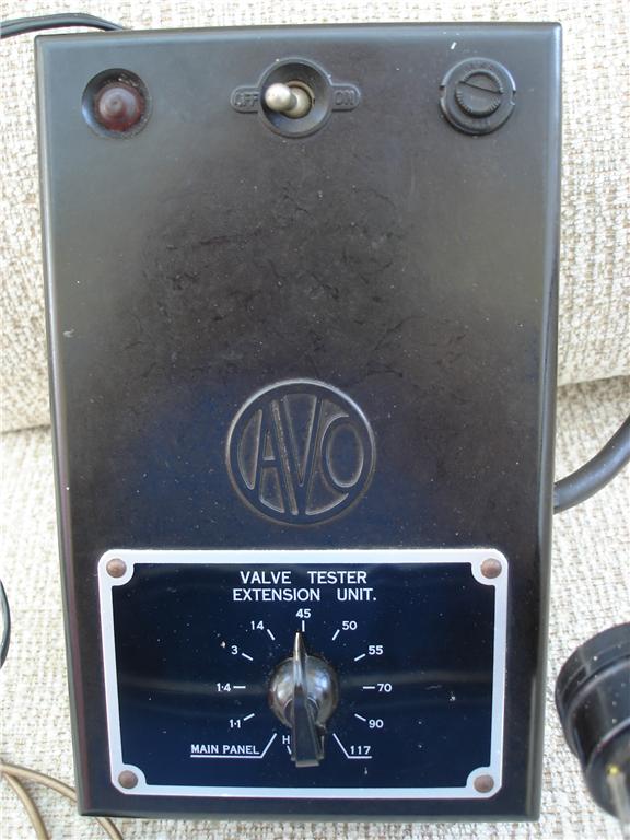
Note the nasty metal cable which attaches the book. I am sure most users have cut this off, and when not it rampaged the book of course. Note, the original AVO Text underneath calls it a Mk2. CALL for information. Please let me know when you have documented facts of any kind |
 This one I know only from pictures. It is a version with the book underneath, with FOUR metal handles, and with holders in the lid for cables. These seem to me some little step into the direction of the Mk3 design. My personal expectation is, this is a later version,
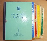
Documentation
Mk1 and Mk2 differ electrically quite a lot, but appearance and functionality is the same. Unfortunately there is little documentation around in the internet. The only complete manual I have seen, was copied by Mauritron UK. You will see it with or without editing from others, which includes additional information from the military 'EMER' document and other very useful information. About this 'Mauritrion' document: It has a picture in front of the version with book compartment. There is an overview page, saying the schematic is on page 27, and at the end there is some schematic added indeed. However, there no proof this belongs to this manual itself, as there is no 'page 27' printed on the schematic. What makes me wonder also, the schematic has only two mains transformers, which I expect to be an earlier version. However, the tester pictured in that manual (see below here) is the one with book compartment and four handles instead of only two. So to my logic this is a later version, which a contradiction. I think we have no good way at the moment to sort all of this out. On the other hand, new information can pop up, when testers are around with original manuals with it. I had that once with a Mk4, and I published the schematic of it, which version was unknown until then in the internet. So you see, this can happen easily.
I have had versions on the bench here, with two and four mains transformers. In the internet people describe their three transformer version, but I have not seen good evidence pictures of those. Do not confuse the Cut Out relay on the schematic with a transformer. What seems a transformer is nothing but a relay with two current inputs. (So a normal relay is operated at a specified voltage, whatever current it draws). The cut out relay is very large, and if you don't know what it is, you will think it is a small transformer. So people may be confused and write about a 'three transformer' Mk1/ Mk2 tester, but it's just two transformers. I don't know, but I would like to see better pictures of that.
I will try to categorize the versions here somewhat.
The late Hein Ros, was an expert on AVO documentation, and never was able to find the official factory service document. So chances it will pop up are low. Yet, the user manual as we have it, is extremely complete, and has a section on calibration. You will be able to service Mk1 and Mk2 with it.
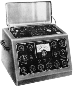
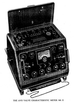
The introduction of Mk1/Mk2
At introduction, this was the Rolls Royce amongst the tube testers. When this tester was the finest you can get in 1948, it still is today one of the best there is. Just they are very old, and need an overhaul to get them back in instrument condition again. With Mk1, all of the good technologies were combined. They had just acquired the Taylor company, and some remarkable details of the Taylor circuits went inside the Mk1. AVO did not have to ask anybody to wind transformers, they had their own facilities. Even today, the Mk1 is fully up to date. You have to add a noval socket if you have the earliest one, but really that's just soldering it in, as the tester was prepared for 9-Pin sockets from the beginning, and the tube data book was updated. So to add this socket, means just tie pin 1 of the Noval socket to pin1 of another socket, etc, and you can take the whole tester apart with just a few screws. So even today, when you use the (latest) Version 23 of the Valve Manual, you can test tubes of the latest kind. This tester had clearly the intention to be a no compromise product. Just name a requirement, and it will have it. It has a large variety of sockets. They can run on 50 or 60 Hz, from 100...250 Volts AC. It can test tubes for Plate current and Transconductance, up to a plate voltage to 400V, or grid voltage to -100V, plate current up to 100mA for amplifier tubes, and any heater voltage from 1.1 Volt to 110Volt. It can test rectifier tubes in a real circuit using a dummy load, up to 250mA. Moreover it features a build in quality test, which works the same as the famous Hickok method.
Since you have full control of everything you are doing, it is even possible to simulate quality tests as other tube testers are doing it. Such as the Funke W19 test method can be replicated, if you get yourself a pdf copy if their test cards, and if you understand how it's done of course.
Mk1/Mk2 do not differ very much in function or appearance, just Mk2 is the face lift version and the circuit is different. Comparing Mk1/Mk2, with Mk3/Mk4, I would say the Mk1/Mk2 is more down to earth. Yet offer the same functionality. If you can do without the fancy looks of Mk3/Mk4, you get the same results, and Mk1/Mk2 is easier to operate, faster, more logical, and the case is lighter weight.
The housing of Mk1/Mk2
Well it's just the housing, but I do want to say, they are more convenient to do maintenance on than Mk3/Mk4. You can just lift off the complete outside housing like a jacket, by only remove fours screws. Unlike Mk3/Mk4, you can also take the bottom off, and the internal chassis is still protected by a frame, and very easy to handle. That is a very large advantage, and I have not seen this with any tester at all.
The housing is made from one plate of aluminum, which was folded such that it becomes a box. The edges were welded together and with great craftsmanship formed round, and brought into the final shape. Vertically the housing has a light V-Shape, to the top is 1cm less wide than the bottom. Probably they used a metal template, on which it had to fit on exactly, so they could slide it on an off. The case was painted with so called wrinkle paint, which is quite resistant against scratching, and it looks very nice too.
Because the housing and internal frame is of aluminum, the tester is relatively light weighted. There is also a disadvantage, the aluminum is not very thick, and it needs to be packed with very high effort when you ship it. So the usual, standard way like Ebay sellers pack it, will definitely end with case damage. However, that damage may be fixed with a wooden hammer, if you remove the case. Whereas Mk3/Mk4, do not damage easily, but if there is damage, it's much harder to repair, because you can't take them apart easily.
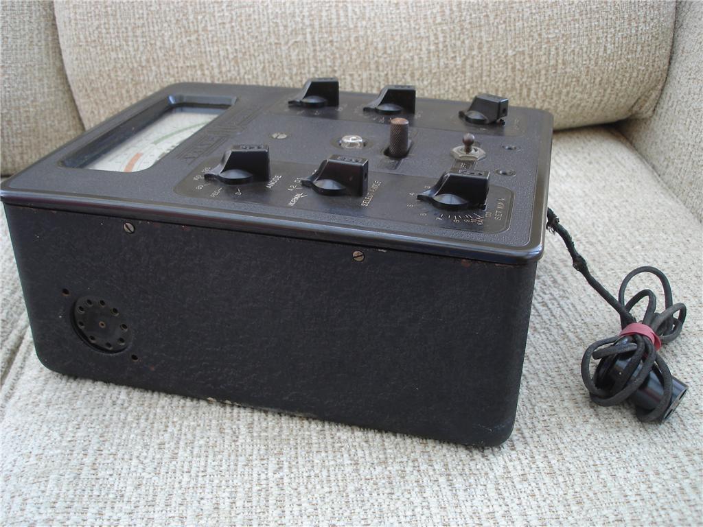
The meter of Mk1/Mk2
The meter is a 100uA type. Not as sensitive as the later Mk3/Mk4, meters, which have 30uA. So measurement of resistance leakage ends somewhere above 10 Mega Ohms. Given, all Hickoks, and other testers with a neon lamp can measure maximum use 0,4 Mega Ohms, you are still far better off. The performance with very low impedance tubes, at high current, is probably slightly more accurate with Mk3/Mk4. However, we talk about a small difference only, and still Mk1/Mk2, are excellent testers. To my opinion, Mk3/Mk4 are not worth their 2x higher market price, but markets are not always driven by logic. It's just how things are.
Like all AVO's the whole tester works bad when the meter is bad, but meter of Mk1 is 100uA is more rugged than the 30uA meter of Mk3/Mk4. . Yet it can be defective, and a bend needle you more often find it, as not find it. So check out the meter, is the #1 action for an unknown tester.
The Mk1/ Mk2 metering is done different. With Mk3/ Mk4 you have a series resistor of 199 Ohms in the test circuit, and a very sensitive, high impedance panel meter is across this. Whereas with Mk1/ Mk2 rather the panel meter itself is low impedance. I think both systems have their own advantage. The specifications of the Mk1/ Mk2 panel meter is found officially nowhere. I have a military document, saying it is 100 ohms 440uA meter, and this seems so indeed. Only I cannot promise that is so with all Mk1/ Mk2.
How do these testers work?
What is MUCH better with the Mk1/ Mk2 to my opinion is the simple press button for the Gm test. So when you made some kind of mistake, you let go the button, and you are back to Plate Current mode again. With Mk3/Mk4, you need to rotate the test knob, back to plate current again, and that is just not as fast.
What is backing off? This is the AVO method, which they took from the Taylor testers, but AVO does it more straight forward. This is used to measure Transconductance directly in mA/V. It works very simple. Suppose you have a tube under test, with a Transconductance of 2mA/V at a particular setting of let's say 8mA. If you change the grid voltage 1 Volt, this will increase the plate current to 10mA. To make this possible, the meter itself (so not the tube) can be set to zero, just by adding a small voltage to it. The tube is still at 8mA. This step is called backing off. Now, you press the mA/V button, and you can read directly the transconductance. Logically this is on the 10mA scale, but you can change the scale, just as you like. Then, release the mA/V button, and go to the mA/V setting, press it again, and now you can read the quality of the tube on the good/Bad scale. Or, press now the 'gas' button, and read the Grid current directly in uA. When you practiced it a few times, you'll find it quick and logical.
Gas Test. There is no way what so ever, to measure the gas in a tube, after the vacuum pipe is sealed. So afterwards, we can only say it is very much or very little, and it is derived from the tube behavior. Gas is a pressure, and today expressed Pascal, and historically in Torr. There are a few ways to get a result, but generally when a tube has gas, it will also have grid current. (Positive, electrical current comes out of the grid. So electrons go in). Measuring grid current in the range of less than 500nA is difficult, yet defect level is around 1uA. A very simple method, is to add a resistor in the grid circuit, and there will be some voltage across it, when there is grid current like 2uA through 100k will give 0,2Volt. For some tubes, that is nothing, but other tubes will draw more plate current if the grid voltage is lifted slightly up (so less negative). So the common gas test in cheap testers works this way, it is only a resistor with a switch in parallel. However, this does not tell is the grid current in uA, also and it ignores the way the tube reacts to this small voltage. Like for a 300B you will see only 1.5% change, but for a 12AX7, 200mV grid voltage change, means 25% more plate current. At AVO they use a unique method. The tube itself is used as a measurement amplifier. The way they do it, is very clever. First, the tube is set up in a normal test. So a tube like 12AX7 is set up for say 1.2mA plate current. If it draws more or less, is not so important, as long as you are aware, you test grid current at that particular plate current. So it is better, to change the grid voltage such that the normalized plate current of 1.2mA is drawn. Now, the plate current indication is set to zero, by giving an offset signal to the panel meter. So the meter is now at zero, but the tube is actually at 1.2mA. No comes a calibration procedure (look here for details). So you need to do a few settings, which effectively uses the tube under test as a calibrated amplifier. After calibration, the meter is now 10uA full scale grid current. Press 'gas' and you have the result. It is really remarkable how nice this works, and also how they set up a 10uA Full Scale measurement, using a 440uA panel meter. Moreover, datasheets that do specify gas test results, always give this as uA grid current. Perfect - and this is exactly what we need. All AVO tube testers starting with Mk1 can do this. I will not say, there are no other testers capable of this, but myself I do not know one.
Faster results as with Mk3/Mk4, Part1. The difference is really significant, and I would like to pay some attention to it. With Mk1/Mk2, after backing off, you can DIRECTLY read transconductance on the meter scale. With Mk3/Mk4, cannot! There is a step in between, you need to adjust the Gm wheel until the needle is in the green center mark of the meter, and then you have to read Gm from the dial wheel. To me the Mk1/Mk2 procedure is a lot more logical, and faster too. Besides, reading Gm from a meter is nicer than reading it from a dial wheel. The fans of Mk4 calling this best tester from the Mk1....Mk4 series, are not wrong, but Mk1/Mk2 have this remarkable faster process, and I have to say, I prefer Mk1/Mk2 because of that.
Faster results as with Mk3/Mk4, Part2. What is also better with Mk1 /Mk2, is the backing off is done with only one pot meter, vs two pot meters in the Mk3/Mk4, where these often too sensitive against tapping. So you do the backing of, and right after it becomes already instable. If you just tap in the tester, you may need to do the backing off again. Also operating two pot meters is just tedious. With Mk1/Mk2, there is only one pot meter, which is actually internally combined of two pot meters. This makes it logarithmic, though wire wound. I have to say, this works much better! The backing off is done quickly and easy, and is immediately stabile. To my opinion, this is a large disadvantage of Mk3/Mk4, and Mk1, M2, does not have this. Owners of Mk3 and Mk4 will know, with two pot meters, you sometimes forget to set one of the two back to normal, that will bang the panel meter in the corner violently, if you begin a new test. You can do this wrong with Mk1/ Mk2 as well, but with only one pot meter, risk is lower. Add to this, Mk1 Mk2 doesn't react much less violently, and the meter is less fragile anyway. That explains why Mk1/Mk2 meters are normally still good.
Cleaning an old Mk1/Mk2.
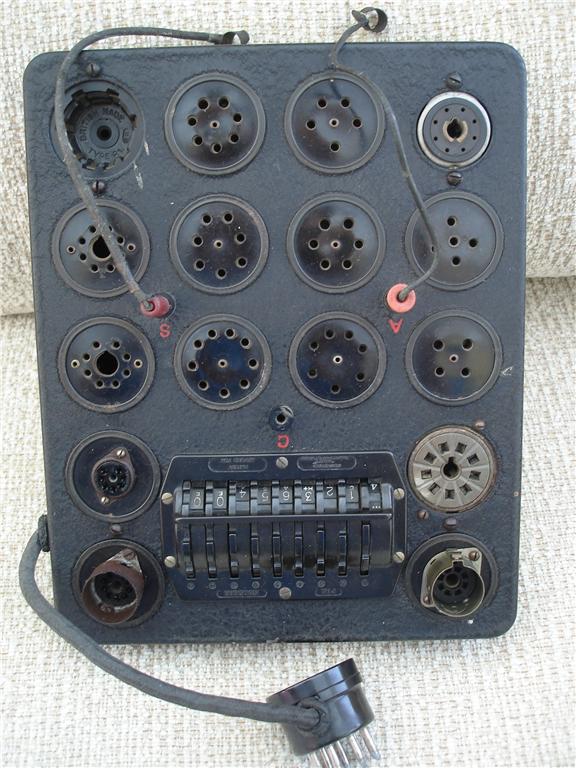
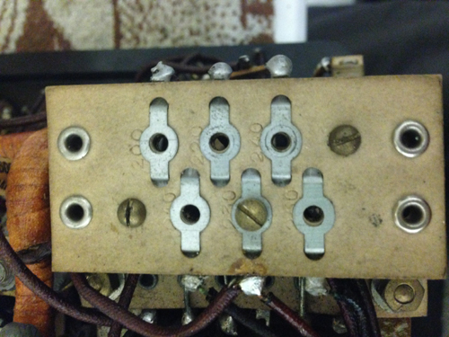
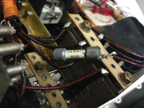
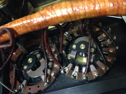
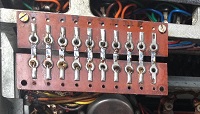 All sockets are tied together with their corresponding pin numbers, just as in the socket data book. From there is goes to the roller switch, and the outputs of the roller switch go to this soldering panel, pictured above here. Like that, the electrodes, so G1, G2, G3, etc, of a random tube, are always at the same position of this soldering panel. So the whole wire mess of sockets wiring and switching, is solved directly underneath the socket panel, and from there to the solder panel. From here, it goes nicely ordered into the tester. You can't say that from any other tester, and frankly the wire spaghetti is often is terrible to work on. Also you can remove the entire deck plate completely, for cleaning, which is the standard work I do with every AVO I get. Such simple things as a few drops of coffee inside some sockets can give you trouble, and also dust, which tends to combine with fungus over time, it not something you want to have in your socket panel. AVO is the only tester I know of, which can really conveniently remove the panel. I clean it with my own mixture of acid and soap water, and then with pure alcohol to wash out the water. After that dry it in an oven at 60 degrees, and I have an absolutely dirt free and leakage-free socket panel. I take off the roller selector for this, and clean it separately.
Precision and Test results
WIth each newer model and version at AVO, precision has increased, and weaknesses have been eliminated. Yet, progress was only small, which is logical, because already the old 'Valve Tester' was a very good one. So don't think you buy 'old junk' when you buy a Mk3 instead of Mk4, or a Mk1 or Mk2. They are work comparable, and results are comparable too.
One difficulty AVO never talked about, is these testers are not good with very low impedance triodes, at high current. Such tubes are very few, and the error is seldom very large. Yet when you look up the 6080 in the valve manual, you find a small remark there: cannot be tested, due too low impedance. So that's the item. If you do test such tubes, at high current, there will be too much voltage drop over the current sense resistor, and even when just a few volts, the lower voltage tubes like 6080 will react on that, with quite a change of current. So effectively, the tube is tested at lower voltage as intended. The error from this is not small though with must such tubes, and the valve manual anticipates for that, by l test such tubes at higher voltage, and lower current. So at the same dissipation, and then everything will be fine. So to say it again, this is not an item to worry about. I am probably the only one who found this out anyway. A good Mk1 will make you just as happy as a Mk4.
Cleaning, repair and maintenance
People do not realize, but with Mk3/ Mk4, chances on buying one with a damaged meter is very high. With Mk1/Mk2, risk is a lot lower, because first, the meter of the Mk1/Mk2 can handle more overload, operation of Mk1/Mk2, is more logical and safer.
The maintenance when you buy one: The Mk1/ Mk2 is a much older tester, so they all need some work before you have them back into fine condition again. Yet, a Mk1/ Mk2, if all restored, can be your friend for ever. There is no maintenance, apart from calibration every 10 or 20 years. The rectifier are Selenium type. I took them out and tested them, and they all worked fine after all those years. There is general consense in the internet, that Selenium rectifiers are not good, and they warn for poisonous gasses when these get bad, and all kind of trouble. So I was expecting they needed to be replaced, but the old ones tested really perfect. No leakage at all, and very well defined 'on' voltage of appr 40V. I have a Tektronix 570 curve tracer for that, so I can perfectly test them. Yourself, you are advised to test them best way you can. Perhaps they can simply be replaced by silicon, but you need to check what that does to the voltages, and distortion of the wave shape. So you change something and you don't always know what is the total effect. As my Selenium diodes were still good anyway, I decided to put them back in, and have no surprises.
Service: Mk1/ Mk2 is very easy serviceable, because you can take off the whole cap with just four screws. So you can access it from all sides. Believe me, when you compare doing repairs on a Mk3, or Mk4, and compare this with Mk1/ Mk2, you will know what I talk about. Mk3 and Mk4 are not very convenient to work on, we have to say it. Though accessibility of components in Mk3 is the hardest. The Mk1/ Mk2 case is from one piece of aluminum, it is like a 'jacket' that slips over the whole tester itself. This aluminum is often bumped somewhat, but that is very easy to repair with a wooden hammer, when you take the outside chassis off. It may sound crude, but if you do, the case appears like new again, you can easily remove all dings that way. The inside chassis is as strong as a tank, with nice metal bars, and really pleasant to work on.
Check list for a Test sequence of a Triode:
The original manual has no quick set up, such as this little card which exists for Mk3. Mk4. So here is the procedure I use.
Note this: The switches have three rows. We begin at the top left. Then in the same order as reading a text, we end at the bottom right switch. Like this we can forget no switch.
- Switch off the tester, insert the tube under test. (DUT)
- Set the roller switch for the DUT
- Mains adjustment switch all to the right.
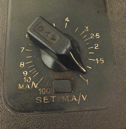
- mA/V to the 100% value for the DUT
- 'Set Zero' pot meter all to the right.
- Electrode Leakage all to the left, on the ~ Symbol
- Meter Selector to 100 in the outer scale. (That is 100mA)
- Circuit selector all to the left at Check(C). That means leakage teste with a cold heater and high voltage off.
- Bottom row, the anode selector to A1.
- Set screen Volt, Anode Volts, Neg. Grid Volts and Filament from the tube data book. Heater switch on the right must be at zero if unused.
- Set the multiplier for Vg accordingly 1x or 10x if not done yet.
- Switch on the tester. The scale must be backlighted. If not, press the Reset Switch, or check the fuse. If backlighted: continue.
- Adjust the meter for the ~ Symbol. Use the SET~ switch for that. If you have problems with the range, the tester may be set for the wrong mains voltage at the back.
- Now the tester is ready to begin with a few low voltage tests.
- Step the Electrode Leakage Switch clockwise, and observe the meter. At 'H' it must indicate a full short (close to zero ohms) indicating the heater is not open. At all other settings it must be high impedance. For amplifier tubes, skip D1, D2, that is for diodes only.
- Set Circuit Selector to Check (H). This will turn on the heater. Wait until it is nicely glowing, and repeat the previous step, this time with a hot heater.
- Set Circuit Selector to C h-k. This checks heater cathode leakage, here for the tube with cold anode still. This is an important test for noise, so don't skip it, specially not the hot part, which comes later.
- Now comes the High Voltage testing. Set the circuit selector to TEST, and Anode current should be indicated. Adjust the meter selector for a more sensitive scale. Wait until the tube becomes stabile, and read the anode current.
- Turn the Set Zero knob to the left, until the meter is at zero. Now press the mA/V switch and read the result.
- Optionally a Quality Test test can be done.
- Leave the Set Zero knob at the right position and set the Meter Selector to mA/V.
- Adjust the meter for zero with the Set Zero button
- Press the mA/V button. 100% Gm it will indicate in the center of the green scale.
- Optionally a Gas Test can be done. (Grid current test)
- Set up a normal tube measurement.
- Make the tube draw the normalized plate current, and leave that as it is.
- Set meter to zero with 'Set Zero' knob, while pressing mA/V button at the same time.
- Set meter selector to mA/V. Set meter to full range, with 'Set mA/V' knob, while pressing mA/V button.
- Release mA/V button, and press 'GAS' button. Full scale is now 10uA grid current.
- Set the circuit selector to C h-k. Check for no leakage, this time for a hot tube
- Set Circuit Selector to Check (H). Check for no leakage, this time for a hot tube. At this position, the meter may even turn to the left slightly, which is normal, indicating emitted electrons, even without voltage applied to the tube. In Check (H) position this should disappear after the heater cools down.
- Finish the sequence by setting the Circuit Selector to Check (C)
- Accidental Meter damage can result from leaving the tester at too sensitive range. To prevent this, after a test, set back the Set Zero Switch to the right position always.
Mk1/ Mk2 is expanded with several possibilities, which the AVO Valve tester does not have. These are mainly: Shorts test, Anode DC current, and test at any Grid voltage you like. Furthermore, the maximum anode and screen voltage was raised to 400V with the Mk1/ Mk2. (The AVO VALVE TESTER had maximum 250V). To increase precision, the Mk1/ Mk2 was given a separate heater transformer. So any heater current draw will not make the anode voltage drop. Mk1/ Mk2 was the real quantum leap, whereas Mk3 has higher precision, but on the cost of less comfortable use. Like Mk3 has one 'fine' and one 'coarse' pot meter for the backing off, and Mk1/ Mk2 has only backing off pot meter. Yet backing off with Mk3 / Mk4 is often difficult and overly sensitive when they get older, and this is often hard to fix. Even so it turns into a quality item for Mk3 or Mk4, so you want to know always: 'is the backing off still good?' Whereas Mk1/ Mk2 with only one pot meter can be backed off good enough, and for sure a lot faster as with Mk3/ Mk4. Also, testing of Gm and Gas, with the push buttons of the Mk1/ Mk2 seems more logical to me. Mk1/ Mk2 has a beautifully back lighted panel meter. So not just with a side lamp, but nicely with two radio scale lamps from behind, through the meter scale, which is opaque. Actually already Mk3 is missing the backlighting feature, and I can tell you this is really better with the Mk1/ Mk2. In case of a fault, with Mk1/ Mk2 the white backlighting goes off. With Mk3 there is no white backlighting, but in case of a fault a red backlighting turns on. I prefer the Mk1/ Mk2 method.
Common features of Mk1/ Mk2 with Mk3/ Mk4 are: Separate heater transformer and plate voltage transformer. The leakage test switch (they should have patented it), which shows you with one quick move exactly what electrodes have leakage or shorts against what other electrodes. A short is zero ohms, and leakage is represented directly in Mega Ohms, while tested with high voltage AC, yet limited in the uA range.
While tube testing, you can directly see the Plate current in mA. Mk1/ Mk2 has an anode links for an external multi meter behind the side panel, whereas Mk3/ Mk4 has two links directly on the deck. That is sometimes very nice to use.
Anode and Screen voltage up to 400 Volt. Plate current up to 100mA. So yes we talk about 40 Watts here. It can do any heater voltage, and any mains voltage. It features a protective relay with a hold function, and it has sockets for a remarkable large variation of tubes. We still talk about things that Mk1/ Mk2, Mk3/Mk4 have in common. Inside electronics are not fragile. Resistors and switches are good quality. No strange components, that you don't know what it's for. No bad resistors. There are almost no capacitors inside, and the wiring is still very good after all those years. No signs of cracks or anything.
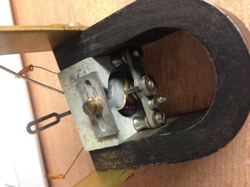
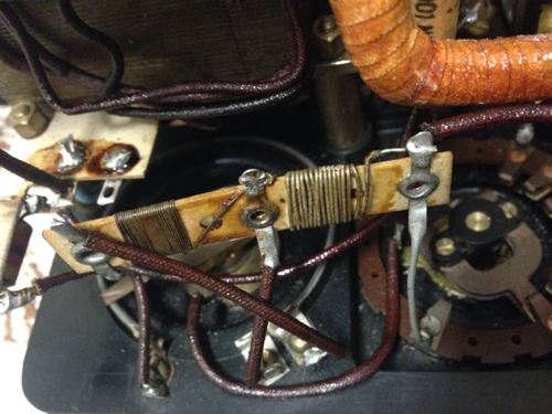
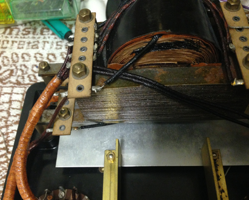
What I like about the Mk1/ Mk2, it has one tube inside which only function is to be a reference tube. So the reference tube and the tube under test go into a Wheatstone bridge, where non-linearity of the tube-under-test is compensated with the non linearity of the reference tube inside. This method with the reference tube is very well done. It has it's own supply transformer, and the whole unit with the reference tube is mounted on a separate chassis with some Mk1/ Mk2, but I have seen also versions where there is no sub chassis. The sub chassis when present, has only four wires. Two are connected to the mains, and the other two are the connections at which a 'reference diode' is presented to the wheats tone bridge. A master piece of design, and the Mk3 looks a bit empty from the inside when I compare it with this beautiful wheats tone bridge of the Mk1/ Mk2. All in all, Mk1/ Mk2 sure is not the 'old tester' it may look from the outside. I really can recommend it. .
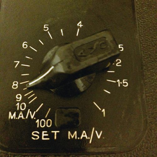
The grid voltage is set with a pot meter, and it has only two ranges: 1...10V, and 10...100V in steps of 1V. Mk3 has steps of 20 Volt, but... the first range is 0...20V. So for low grid voltage, Mk1/ Mk2 may seem better. Though with Mk3 this is compensated with a larger diameter dial wheel, and it comes down to the same. Yet setting for instance 1.2 Volts as you need of a 12AX7, works better with the Mk1/ Mk2 as with the Mk3. Also different with Mk1/ Mk2 is, you have a calibration pot meter for transconductance. Whereas Mk3 an Mk4 don't have that. I really have to say this here, that calibration of Gm with Mk3/ Mk4 is very difficult to do, as this is a factory calibration, no technician job for somebody later. Whereas with Mk1/ Mk2, there is just a simple and normal Gm calibration pot meter inside, and no factory calibration. So the previous owner cannot mess up the factory calibration of the Mk1/ Mk2 because it simply doesn't have any. So you see... don't underestimate the Mk1/ Mk2! This is really a good product.
Add a meter Protection network to your Mk1/ Mk2!
Capacitor protection. Look at the Mk4, they protect a 30uA meter with a 10uF cap and two diodes. I found 22...27uF is a maximum limit. At higher capacitance, the meter begins to interact with the capacitor, meaning it over shoots. In that case, when switching the current off, the meter goes into negative, before going to zero. This can be tolerated as long as it is not too much, and like this a larger capacitor can be chosen. I found a value of 350uF does this good. 8uF as recommended by Hein Ros, has absolutely no effect, and it is obvious he did not test that, but just picked that value from the Mk4 schematic. The Mk1/ Mk2 has a 460 or 440uA uA meter, and not just that, it is very low impedance. The meter I tested had 103 Ohms. In 1950, 305uF was a huge block, and not long time stabile. I think today's capacitors are fine for this application, and given the low impedance of the meter, some small leakage will not affect it. Yet of course, if you use such a capacitor, occasional testing of it, like every 15 years or so, belongs then to normal service. It is much recommended, because I have seem many meters damaged, with the needle being unbalanced, and then the linearity of the meter is bad, or it has a stick-slip problem..
Diode protection. Let me try to clear the biggest misconception of all, when using protection diodes. People use small diodes, to protect the meter. Like 1N4148 or glass Schottky Diodes, because from 1000 people, 999 think these diodes give lower forward voltage at lower current. This is absolutely WRONG. There is little point in trying to imagine how this must be, when you own a multimeter. In that case, you can measure it instead. I have to say, I was surprized to find very heavy Silicon Power diodes, across the 30uA meter in the Mk4. So I though at first, how primitive! Kick out that old fashioned junk, and replace them by nice 1N4148 glass diodes. Then, I compared forward voltage of those, at LOW current of 300uA, and much to my surprise it is a LOT lower with those fat power diodes. I thought, perhaps those were Germanium diodes, so I made a Voltage-Current plot with the Tektronix 576 curve tracer. But no, they were Silicon diodes. What was the conclusion? Those big rectifier diodes, I estimate them 6 Ampere types, have indeed the normal 0.7V at 6 Ampere, but 0.5V at 500mA, and even much lower in the mA range, and no measurable reverse leakage at just a few hundred mV. Whereas the tiny 1N4848 also has 0.7Volt, but in the range of mA already. So indeed, using a diode as a voltage clamp, works much better when the chip is larger. Which makes sense to me, because small diodes are just smaller pieces of the same wafer, from which the are cut. So a big diode acts as many small ones in parallel. I would say for the more rugged Mk1/ Mk2 meter, a 1N4004 diode is a good choice, and 1N4148 is too high impedance.
AVO Valve Manuals - Manual of AVO Mark2 Tester
In a few words: For me Mk1/ Mk2 is a great tester! FIVE STARS *****
 AVO Mk3
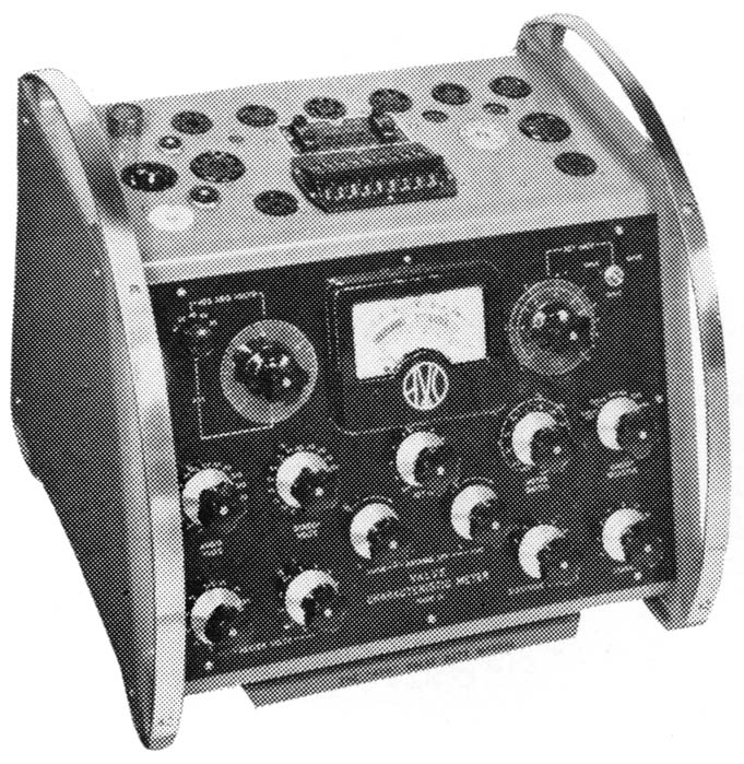 Mk1/Mk2 was the quantum leap, it was the first 'big' tester which can do everything. Mk3 performs the same tests. The MK3 case was optically a big change, and precision was slightly better, but that difference is not very high actually. Moreover there is some loss in comfort with the Mk3, as with Mk1/Mk2 you can measure Anode Current and transconductance just by pushing a button. It has to be said, this great comfort got lost with the Mk3, and also with the Mk4 of course. Mk3 looks definitely nicer and the case is more rugged. However, for repairs, you cannot take the case off completely off, because it is a self supporting structure. So the more panels you take off, the more loose the construction gets, and it would fall apart. Whereas with Mk1/ Mk2 you can take the whole case off, like a jacket. This is really a big change with the MK3, the nice looking case, which is bullet proof, but you can't take it off. Also the board with the calibration pot meters on it, is reached a bit difficult. This board position was improved with the Mk4, but you can't take the Mk4 out of it's case also.
Mk4 came after the Mk3. First be aware, the Mk3 and Mk4 differ not much. Mainly the Mk4 has a more 'fancy' way to set the dial wheels with a 1:20 gear, and Mk4 has silicon diodes to generate the DC Voltage inside, where M3 has tubes and Selenium rectifiers for that. That is all. However, the tubes and Selenium rectifiers of Mk3 I have never seen a case where these were defective, and the 1:20 gear of the Mk4 is just marketing, because behind that is just the same potentiometer as in the Mk3, and you can't set it more precise by adding a gear to it. So frankly, consider Mk3 and Mk4 quite the same.
About the Mk3 now. This tester looks different, but similarities with Mk1/ Mk2 are many. The face lift is the case itself, nicer arrangement of the knobs, and nicer looking knobs with plastic dial wheels for the grid voltage and transconductance. Also the case is now idiot proof, which is a great advantage for the average user, and of course for the transportation experts of the post office as well. Mk3 has the more sensitive 30uA meter, which is a advantage and a disadvantage. The advantage is, the 30uA meter allows 3x better sensitivity with leakage test. This makes the Mk3 such a sensitive device, you can even use it for transformer or cable leakage tests, when you know how to do it. These meters However, are the 'standard' problem with Mk3 and Mk4, as the tester is probably used in it's 70 years of existence by many people, There have been always one or two who were not interested in what they do. If you want to find out by trial and error how this tester works, that's the beginning of trouble. Leaving behind a still working meter, but with linearity errors. Any meter damage can be not seen quickly from the outside, or derived from it's function easily. Somebody will notice at some point the tester is inaccurate, and begins to calibrate it, with a bad meter inside. However, there is no way, to make a tester work good, with a bad meter inside. So eventually the tester gets put aside, often for a few decades, and then gets sold on Ebay, 'as is'.
Such meter problems do exist less e with Mk1/ Mk2, as these have a 100uA meter, which is more rugged build.
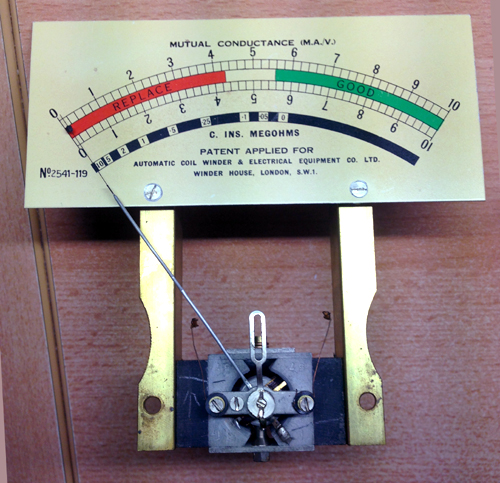
The panel metering system.
This is a big change compared to the Mk1/ Mk2. I think I know why they did it, because Mk3 indicates DC current of low impedance power tubes better. This is really the change Mk3 offers. The meter of the Mk1/ Mk2, is a very low impedance meter, and Anode current flows for a great part through the metering system itself. Whereas with Mk3 there was used a copper wire wound current sense resistor of 199 ohms, and the voltage across this resistance is measured to determine the plate current. As you can see, voltage across 199 ohms is very low at 1mA only. So the panel meter of Mk3 needs to have very high sensitivity. The panel meter is 30uA full scale. Which at those days was a masterpiece of meter design, and today it is even more, as most factories that can make high quality meters, have disappeared. The Chinese still sell cheap 30uA meters, but these have too high impedance, they're not very good in reality.
How did they increase the meter sensitivity?
Well, one way is to make the circular hair springs very fragile, and low force. However, this makes the meter problematic with respect to dirt particles, friction and electrostatic loading of the needle paint and glass. Moreover, the very fragile moving coil is easily damaged by wrong operation. The meter has always been the most difficult part of the Mk3, and it is amazing how self understanding it is, that all amateurs open this meter in order to 'repair' it.
Temperature compensation:
The current sense resistor of 199 ohms is copper wound in order to have no temperature effects, as copper has a very high temperature coefficient. This sound like a contradiction, but it is not. Because the wire of the meter coil, and the calibration resistor inside the panel meter, is copper wound too. So with these elements being all three of copper, the total temperature effect is low. The current sense resistor will burn out sometimes, when people put 250mA rectifiers under permanent test. Then after half an hour or so, the isolation burns, and some windings may short. A repair should be done with normal copper wire. So do not replace this 'strange' resistor with a nice ceramic precision resistor, in an attempt to 'improve' it.
Buying advise:
The dial wheels should not be badly repaired. Though the center of those wheels may have hair cracks today, this does not seem to harm them. In case you do need to replace one of those wheels, you can make one yourself from a knob of any other AVO Product. Sometimes you see some kind of old AVO products on Ebay for 30 Euro only, and you can take off one of the knobs. Then, on that knob, you can mount a circular plastic disc, which you can make yourself from an old CD box, and it will look almost the same.
Beware for a defective meter.
I can't repeat this often enough. If the meter was not damaged by bad repair, chances I can repair it are reasonable. If not, a replacement meter is available, but expensive. I have to buy r the movements on special order, construct a new scale for them, and change the impedance and full scale sensitivity to the AVO specifications. Yet, one ready to use meter is usually on stock. Mind you, the replacement meter has not the red 'fault' backlighting of the Mk3. As this is a plain 220V light bulb only, you can find a solution for this, with an additional panel lamp. Or, we can add backlighting inside the replacement meter itself. The electrical connections for this is simply in series with the light bulb of the Mk3.
DIY repair of a Mk3.
Though schematics (and people like me) exist, repairing those is difficult. So do not think you can quickly fix the problems on a 3unday afternoon, when the previous owner gave up on it. Like I always say, better buy a good one, and pay more for it.
Still, when you are the owner of a nice and good working Mk3, don't sell it! It will be your best friend for decades.
In a few words: FIVE STARS *****
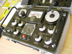
AVO Mk4
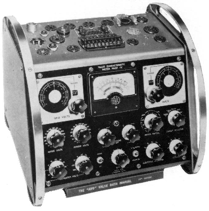 So here we are: The most wanted tester. Also the one that is most often worked on by unqualified people.
Mk4 has only small advantages over the Mk3, like more precise reading of the scales, if you believe that. The Mk4 is the fourth generation testers of this kind. Very mature, as a result of many years of development, and all errors of the earlier models were solved. Mk4 is all solid state, though I have to say I have had Mk4 here with damaged diodes, but the tube diodes and Selenium diodes of Mk1/ Mk2 and Mk3 were never bad. At least not with my testers.
It can test almost any tube. (Mk1...3 also) The extremely sensitive isolation test is seen only with the Mk3/Mk4, CT160, and VCM163, and for the rest with no other tube tester. The shorts' rotation knob is a method worth an extra patent. (see details about this at Mk1/ Mk2). The Funke testers do the same, but the Funke switch is sensitive to wear out. The Neuberger also do the same, but with a far too complex switch, and specially the older models all suffer from material detoriating.
The case of the Mk4 is dairy piece of industrial design work. You must imagine the thing 50 years ago, it must have been kind of fancy to have one. Even it is today. It is not as easy to service as the Mk1/ Mk2, but you can work on it, if you don't need to dig deep inside. They do need a bit of service, all of them now. The backing off pot meters can be dirty, or have faulty spots. Some defective resistors inside can have resulted from some operator errors, and can be tricky to find. Like you can burn one resistor, and then the whole grid voltage ladder is out of calibration. The big carbon (10%) resistors are off value often, but these were used for uncritical functions, and replacing those doesn't make the tester any better. All other resistors are precision types, like 2%. Sometimes a diode can get broken, but that is easy to find.
It must be said, when a MK4 is well restored, it will last a lot longer and the quality of all parts inside is still good today. Please read the buying down here. It sounds unlogical, but my experience is, the Mk1/ Mk2 and Mk3 have the lowest problem rate. As a matter of principle, defective but working Mk4 are always sold on Ebay, and buyers find out much later, often years later, it has been messed with.
Is a Mk4 better than a Mk3?
No, I don't think so. Mk4 has solid state diodes, which can be defective too. Mk3 has tube diodes, and they seem always good. Mk4 doesn't have the red 'failure' backlighting function of the panel meter anymore. This is a very nice feature of the Mk3. And it was removed with MK4 and no replacement. It really wakes you up when you make a mistake and the whole tester begins to buzz loud, and the Mk3 meter suddenly lights up red. (There is a very bright, red lamp behind it) Of course you want to switch off the tester quickly, but there is no need, it already is deactivated in this condition. For the rest, differences are small. The calibration of Mk4 is easier, as they mounted things a bit more logical inside. For the rest, Mk4 and Mk3 do not differ very much. Mk3 has no gear on the Vg and Gm wheels, and with Mk3, factory calibration is nothing but change the position of the scale. You should NOT do that, unless you exchange the pot meter, but you can tell that to all those people who own a set of screwdrivers. So restore the factory calibration with a Mk3 is quick and easy, vs complicated and time consuming with a Mk4.
Some advice for buyers:
Unlike most testers, electronics inside Mk1...4 is somehow logical. Though not self explaining. What is not working, just general experience and do a 'quickie' repairing an AVO. It is very full and compact inside, and you cannot conveniently open it up. People do not want to hear it, but the calibration procedure is NOT working well if there are other problems inside. They all try to skip as many things as they can. Often, new owners just fiddle with the calibration screws and think this will change an inaccurate tester into an accurate one. I am trying to tell you here, you better pay more for a good one, than pay less for the usual ones with the vague promises only.
Damaged or sticky meter. Check the meter, by performing a leakage test with the tester. Use a potentiometer that you connect to two pins of a tube socket. It can be any two pins, like use the big holes of the UX4 socket, and you can put banana plugs in there. You must be able to measure exactly the pot meter values with the AVO. If this reproduces, that means a lot for a good panel meter, and for the rest of the tester also. If not, you have a problem with the panel meter most of the time. So take a 2 Mega ohms pot meter for this, and measure with the AVO it's value at several settings. If you are surprised, this is possible at all, you have not read the handbook. This is what I meant to say above, when somebody says from himself he is an experienced user. Linearity can be terrible, and the panel meter inside partially damaged by short circuited tubes, or somebody forgot to set the backing off switch back to zero, after a test. They're very sensitive meters, not made anymore. Some CT160's are often slaughtered to get the meter out for repairing an AVO Mk4. Then the bad Mk4 meter gets put into the CT160. All thumb wheels must run smooth, and printing on the wheels must be clear. A non-smooth thumb wheel is very difficult to get smooth again. The wheels may have absorbed oil or dirt, and may have got a very small fraction thicker. So, put oil on it, helps not much, or makes it worse, and only resolves the lettering paint. Voltages: Take a multi meter and check each and every voltage. Values are not what it says on the switches, so in good relation with the other voltages is all you need. Only for the heater, the voltage must be as on the switches. Set the mains test mark, and then you need to see 6.3V with a 6L6 INSERTED. Just as a quick test, because real testing (and calibration) of the mains mark is done totally different! At least with a 6L6 inserter it should be close. Precision of the plate current test should be better than 10%, to justify maximum prices. How is that verified? You need a calibration tube of type 6L6 for this, with tube curves, to verify the tester at various points. Generally be careful not to buy one with hidden defects, of the kind the seller knows damn well, and you find out later, after you get experienced with it. Precision of 20% I would say it is normal and you can sure that. Below 30% is very much. A very used case, doesn't mean anything at all. What should impress you is PRECISION. Not shiny looks. OPEN IT UP before buying. Just four screws. Now check very very carefully for traces of repair. If so, that means there was some problem, because maintenance is hardly needed. So you have to hope he found the problem, and fixed it professionally.
Ebay prices seen:
2007: 'good' : 1600€
2007: no meter and defect: 600€
2010 EUR 3.662€ (Auction 370415230702)
2012-Dec 5607 US$ (Auction 370706510866). (Mint condition)
2012-July 4458€ (Auction 140803614222) (Mint condition)
2022-Feb. 2800US$ (Auction 224448738907) Rusty Case, defective Meter.
In a few words: FIVE STARS *****
AVO CT160
Ebay prices seen:
2007: Very good one. 1675$.
2007: Probably good. 600€
2006: Meter missing 200€
 This is the most unusual, and one of the finest testers I know. This tester works by a Wheatstone bridge principle. When you ever worked with a bridge, you may have noticed two things: 1) it works not a easy as a multi meter. 2) They are awfully precise. The reason for the precision is, the panel instrument is only needed to 'zero' the bridge, and the actual precision and linearity of the panel meter becomes irrelevant. Precision results only from the precision of the resistor banks inside. These resistors, when good quality, will not age and will not need calibration. Same with this AVO CT160. You have to zero the meter by using the set knobs, and once that is done, you can read the plate current from those set knobs. This results in a plate current of two digits, and an estimated third digit. So instead of reading current from the meter, it is only used to 'zero' the bridge. So the three knobs for instance would read 97.2mA plate current. The interesting part is, the third digit (here the .2mA) occupies a length of 1cm on the analog knob. So you can very easily estimate the difference between 97.2 and 97.4mA. On a normal 100mA panel meter you will never be able to do so, as the difference between 97 and 98mA is one stripe of 0.7mm wide. (vs 10mm with the CT160). Even so, a panel meter has 1.5 % error, whereas any error of the CT160 panel meter is irrelevant.
Once you get used to the bridge, you will do a measurement quicker as with the Mk4, as the nasty backing off is not needed. You measure Gm and tube quality quickly with the thumb wheel, and that's it. So the CT160 works faster, and is more precise. It's just not 'main stream' and it will never be.
Advantages: Lower weight, higher precision and lower cost as Mk4. Less parts, so less can get broken. All critical parts are put together on a side board. So you can miss that. Just test them on this board one by one, and likely the tester is ok then. When you close the lid, the tester is closed dust proof, by a rubber seal, and that makes usually the inside panel is very clean, and inside the tester itself it looks like made yesterday. Needless to say, this cleanliness does good to the whole product.
Disadvantages: Unusual operation. Grid voltage limited at -40V. (Though you can add -40...-80V option yourself easily). It has no 'shorts' test, but it does have the usual leakage tests like cathode to heater.
Restore: There are few enthusiasts who restored a CT160, and the case can be nicely taken off, and all hardware taken off, and then repaint it with car spray. All screws and handles, etc is nicely chrome plated, and comes out like new, when you clean it with a mixture of 25gram citric acid (very cheap on Ebay), in half a liter of water, and add half a tea cup of vinegar, and a tea spoon of liquid soap. Put the parts in there, not touching each other, so you won't have any electrolysis effects. Observe it, so it won't be in there longer as needed, otherwise you may get stains.
Typical defects: Grid pot wire interrupted. This is a very special potentiometer, replacements are absolutely unavailable. I may be able to repair the pot for you. Better not try it yourself. Meter can be sticky, or needle damaged by foolish operation. When the meter is still moving I can usually repair it. Replacement meters can be ordered via our company.
CONCLUSION: Amongst the top-ten testers. FIVE STARS *****
For a detailed report, click here.
AVO VCM163
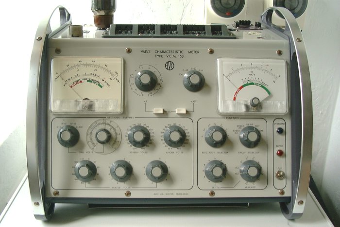 This tester is the Crown of the AVO tube tester developments, and at the same time ended the development of this product line. Though there was a table top prototype called VCM161, which did not make it into production. The VCM163 improves the Mk4 at a several points. It has an internal test oscillator with Germanium transistors. When looking at this board, I suppose it would need new capacitors one day, but mine works fine. The oscillator makes it possible to measure plate current and transconductance at the same time, and also you can see in real time how transconductance goes up when you increase the plate current, or play a little bit with other settings, such as heater voltage. This is definitely an advantage over Mk1...Mk4, since the back up procedure is now obsolete. So as easy and quickly as you can see plate current on the Mk1...Mk4, now with the VCM163 you see at the same time transconductance on the right meter.
Grid voltage setting: Like I always say, this thing with the gear wheels on the grid voltage of Mk4, to my opinion was a marketing feature. This only makes calibration more difficult. It was removed again from the VCM163. Very good. The 'feel' of the grid pot is excellent, as precise and as good as with the Mk3 again.
Panel Meters: The unique ultra sensitive leakage test of the Mk4 is missing. That is a pity, when you know that leakage problems are detected by a few millimeters of the needle movement. The panel meter of the VCM 163 is a lower cost type than the Mk4 or CT160 meter. Also the meters are not the same quality as we are used from AVO before. This is strange. The covers are now of plastic. I am not an expert on plastics, but I recognise this particular plastic l they used here, also from other meters and older products. It is not very strong and tends to crack when it gets older. Also the covers may have become scratched, and then polished by somebody, who cracked the plastic. You can just clip off those caps, and then it becomes a big temptation for some fools trying to do something 'good' to the movements. Moreover, the covers are not dust proof, this is really silly. Dust is always aggressive, forms an oxide layer, and is food for fungus. I am glad to say, my VCM163 is fine, but when you can buy one with some 'small' meter issues, changes on defects are close to 100%.
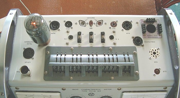 Sockets: At this point, the VCM163 differs very much from the earlier models. The number of socket pins was expanded to maximum 13 pin sockets, and also two top caps or side caps for a random type of connection can be selected. This makes the number of dial wheels 15 versus only nine with all previous models. This higher number of dial wheels may look inconvenient at a first glance, but in fact it makes no difference, because for 7 pins sockets you only need to set the first seven dial wheels.
What is good however, settings for those older sockets are in the data book, so you just need to build them inside, for in case you want so.
A VERY big change is, the number of tube systems within one bulb is expanded to three anodes in case of amplifier tubes, and even four anodes in case of diodes. Even so, they found a way for the user NOT having to change the dial wheels all of the time.  This is really quite exceptional, and I know of no other tester which can do this with four anodes, and offer such great convenience still. . So we all know the A1 - A2 switch of AVO Mk1...MK4, in case of a double tube. Well, with the VCM163 there is now the A1- A2- A3 switch (actually labelled: aI - aII - aIII) for a triple tube, for instance like the 6Q11. It's a bit off-topic here, but 6Q11 is a magnificent tube. It has the two systems of 12AX7 (ECC83) and one system of 12AU7 (ECC82) in one bulb.
The way the switching for this was done, inside the tester itself is completely new. It is not like we are used from the Mk1...Mk4. With VCM163 double and triple tubes are all in parallel, with exception of the control grid. So that applies for the anodes, cathodes, and screen grids. This simplifies the tube selector switch wiring very much. However the dial wheel settings are not compatible with Mk1...Mk4 (and VCM160) for that reason, and later valve data books have one table for Mk1...Mk4 and one table for VCM163 only. When anode 1 is measured with VCM163, Grid 2, and Grid 3 are given a very negative grid voltage for this tube, which cuts of those systems. Only Grid 1 has the right voltage on it. So effectively only System 1 is tested, and System 2 and System 3 (if present) are cut off by very negative grid voltage.
Another VERY big change. Many of the vintage sockets are missing. This is really BAD. Why have they done that, as there was enough place om the deck? Strangely in the valve manual However, the setting for the roller switch exist. At least you can add those sockets yourself or make adapters, and then use the valve manual as it. Some designer must have been very sick. I am sure this strange mistake followed the VCM163 since the first day it was introduced.
Roller Switch: It is improved a lot. Much larger, with clear, big numbers I can read that without a lens :) It works more comfortable than the old type roller switch. I noticed the numbers are not printed on there, but there seems to be some plastic foil rolled over it. This may eventually come loose. It is still as new with mine, but it is a good idea to store the tester not in the sunlight. Also that helps to keep the panel meters in good condition.
Testing convenience: As said before, no more backing of. So I can immediately test plate current and transconductance, and with the A1-A2 switch, flip from one triode to the other quickly. So four measurements at once.
Heater Voltage: This is really a bit of a weakness with Mk1...Mk4, for many tubes the heater voltage is a bit too high or too low. That is caused by the number of voltages being not so many, and also because some tubes draw very much current, and others very little and heather voltage changes depending on what tube is tested. With VCM 163 there voltage is simply set with three digits. So do you want 20.65 Volt? Set it for 20-6-5. It's a pity that you can't verify the heater voltage with the panel meter though. This may not even be very difficult to retro fit, because the panel meter has nice scales for that with "30" and "100" on it. The L3-3 uses a push button for this, and we could add such a push button to the VCM163 for the range of 0...30V. That would serve all HiFi tubes nicely. The push button just takes off the two wires of the panel meter as they are, and connects the meter to a rectifier circuit, using a Germanium diode. Germanium has 0.3V forward voltage, but unlike Silicon, Germanium already begins to work nicely at just 50mV. It only saturates at 0.3V but works already at 50mV, and since the panel meter is only 50uA, that works perfect, and voltage drop across the Germanium diode is almost zero at 50uA. I hope to have time for this. Check the Tektronix 576 section for some amazing proof of this curious property of Germanium.
Precision: A dream! This tester is really accurate. I love it.
Conclusion: You probably will end up, adding more sockets to it. In that case make no mistakes messing up the deck plate. So make a good plan of possible sockets to add, and where to put them, so don't waste any empty place. I have not had so many time to test it in greater detail, but it surprises me every time. This tester is an very large step forward, compared to Mk1..Mk4
Price: Very variable because it seems to me not so many are around as Mk4.
CONCLUSION: Amongst the top-ten testers. FIVE STARS *****