(some) Repair notes for the AVO Valve Tester
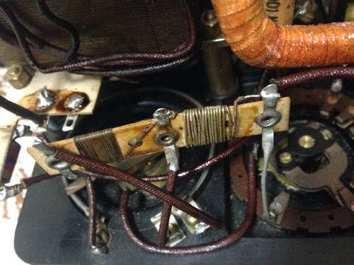
For the Valve Tester, as it’s called, I have never found the factory calibration procedure, but I know from people that bought theirs on Ebay, they write me the tester can be defective. This should not surprise after 90 years. I have two here, which have all original inside parts, and they works so nice, it is amazing. In case you have to do a repair, due to it’s age, the ONLY way possible, is to verify each component by itself. Including the panel meter for linearity. Calibration points.This tester has no user calibration points, which is one of the reasons why this little machine is so genius, and yet works so well after almost 100 years. It has at least one identified factory calibration point, for the full scale sensitivity of the panel meter. This is a had wound wire resistor of appr. 40 Ohms. (So the actual value is variable). There is another such resistor used for the mA/V setting pot meter, and I expect myself this is also a factory calibration. As this calibrates only the pot meter itself, it should be obvious this resistor can not and should not be changed by the user. In the later Mk1... Mk4 testers, this method of factory calibration and user calibration is found as well. So though I write about calibration points, this tester has no user calibration, so it is simply always within calibration. The Panel meter.As with all tube testers, the panel meter is vital for good accuracy, and they did really a fantastic job here. Later panel meters of the Mk1...Mk4 not even come close to the quality of this panel meter. The Mk1..Mk2 panel meter is still robust, but the MK3...Mk4 meters are a bit too delicate (for what some students are doing with the tester). The 'valve tester' meter is extremely rugged, relatively easy to take apart and service. It is a real mA meter, meaning it needs indeed a lot of current. So it is not a uA meter, with a shunt on it as in the Mk3...Mk4. So the magnet is of a type with relatively low strength, and this simply lasts for ever. Yet, as with all panel meters, you are not advised to remove the magnet, as this interrupts the magnetic circuit. This MAY lower it's magnetic force by a few percent, and then the (unknown...) factory calibration of the panel meter has to be done. So leave the magnet in place. This meter is specially build for this unit only. It is no catalog meter, which was build into this tester. In construction and it's unusual large size is similar to the panel meters inside the later 'AVO 8' Multimeter, of which the last were build even in the 1980's. So this construction survived for some 60 years, really amazing. This panel meter is not calibrated by itself, so there is no mA specification for it. There is only the specification for the sensitivity of the meter inside the tester itself, and that is why there is no value with the series resistor of the meter, in the schematic. It writes there only 'approximate' 40 Ohms. So this resistor is the calibration resistor for the full scale sensitivity.
Check the meter for good linearity. If linearity is bad, the whole tester will work bad. There are ways to repair it, but this is specialist work. If you want to learn this, you will sure damage the first meter you try to repair. Like when using an iron screw driver, suddenly the magnet gap catches it violently, and you damage the moving coil or it's hair springs. So better send the meter so someone who has more experience with this. Mains Voltage Setting.I have seen two versions for the mains voltage setting.
There is a Selenium diode in there, which can have loose contacts, and parts lay loose inside. I do not know what is the best way to replace this diode, and I have no particular information about it. You may need to know this: Selenium diodes have a much higher forward voltage than silicon diodes. For the rest, when the a Selenium diode is good, it is a normally good diode. However break down voltage is not very high, and when they needed higher voltage diodes, they just put some in series. So when you find the forward voltage is higher than expected, there is more than one inside, serialized. Selenium diodes are not overly sensitive, but still you have to be careful desoldering it, because Selenium is poisonous when you damage the diode, and it would come out. Yet I leave any selenium diodes in the equipment myself, when they appear optically and electrically good. My recommendation is like how I would fix it: First unsolder it carefully, and restore it carefully. This includes renew the wires on it, or scrape off the mixture of oxide from the wiring until pure copper appears. From there solder plate the wires again, and cool the diode itself by holding a plier on the wire, close to the diode. So after this, you can test the diode. Make the characteristics of it at Max 1/6 Ampere forward current, and check what is the break down voltage in reverse, but I can not tell you at what current that would be. Do not damage it with that. If you think the diode is good, I would put it back in. If you need to replace it, you can simulate a Selenium diode by serialize a 1N4004, a Zener diode and a resistor. This will achieve the original characteristics, but you do need to know the data. If you do not know this data, look up something about 1/6 Ampere types, and take this. There are some people writing in the internet about Selenium diode replacement. Perhaps make some variations, and see if this make noticeable difference. When you are lucky, it makes no difference. Otherwise, you have extra work, as this has to be found experimentally. Bad solder joints.Solid metals are always crystallized. These crystals are never passive. They can split, or they can grow, by 'eating' molecules from other crystals, which get smaller. The speed at which this happens, depends on the quality of the alloy, the used solder flux, the soldering skills of the manufacturer, and the humidity of the environment. This is called recrystallization. If solder joints are totally bad, you can see it, they are opaque, grey and dirty, and when you pull on the solder wire, it gets loose, or even comes our totally. Another problem is 'cold flow' when there is many years mechanical force on a soldered wire it will slowly become loose, even when the solder by itself has not recrystallized. This is why a wire as a minimum has to be out inside a solder lug, with a small 'hook' on the wire, before you put it in. Much better is, to win the wire end one time around the solder lug. It is amazing to see, how people and companies too, simply do not know, and have to learn it the hard way. Here is some more details:
Though generally I find this not a problem with any of the AVO's, I am a bit reluctant with the 'VALVE TESTER', because they are all very old, and I have seen many stored under bad conditions. So you should check the old solder connections. They may LOOK nice, but can be terrible condition, if resistors or capacitors were originally tin plated. Pure copper wires, like from transformers, practically never have solder problems. If bad, just re-tip with a solder iron is like fooling yourself, because this will not remove the oxide from the inside, which is the real reason. Also the older solder in contaminated with the oxide substances, you can not get this out. You need to de-solder with litz, and see if the inside is clean and bright. Only then, you are ok. Just try two or three connections which look not the nicest, and when clean surfaces appear, after removing the solder, probably the whole equipment is ok. A confirmation will come when you re-solder. That should work quick and clean, simply because surfaces were already nicely tin plated before. If the new new solder doesn't immediately flow nice, there was oxide inside. Do not use silver solder on old equipment. That gives an alloy mess, and such connections are unreliable.. Foil Caps need to be checked for leakage, though in MANY parts of the schematic, some leakage may be unimportant anyway, and the capacitance is uncritical too. In other parts, leakage and capacitance play a role. So with some understanding of the circuit, you have to replace only very few capacitors or none at all. Well I just mention this here, but the VALVE TESTER has no capacitors anyway :) The transformersIt should be checked if all voltages are good. Use good judgement, but do not blindly trust it t. Sometimes a winding can be partially shorted, and this particular winding will still work, but voltage is wrong. Rated Anode and Screen voltages on the knobs, are NOT the real AC voltages on the transformer. So when it says '250V' on the knob, a HIGHER RMS transformer voltage will be applied, simulating 250V DC. With simulating, I mean it gives the same test results for the tube's Gm, as if it was 250V DC. Though of course the whole tester works with AC voltage.
Here are the measured voltages on the transformer. Measured unloaded, with the socket unit removed, using a high impedance DMM. The transformer input voltage was 233V. |

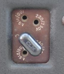 One is with a link, from the side, and it can do 100...115V, 220/230, 200/215 or 240/250V. An older version is has a small lid at the bottom, with a screw setting, which can do 200....250V and it has smaller steps of 10V. So the difference between 230 and 240 is only 4%, but the difference between 220/230 and 240/250 is 9%. So it seems to me they sacrificed some of the precision with the newer version. It is important to set the mains voltage right!