The BIG Test report for ECC83 - E83CC - 12AX7 - ECC803S
JACMUSIC. Since 1993. All rights reserved. Copyright note
Information article about ECC83 and others
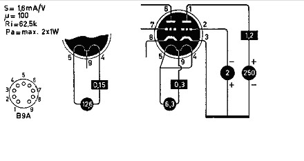
First we start with this standard data, from the Muiderkring book. This datasheet shows the way an ideal tube would bias. The complete book you find on www.4tubes.com. Make good note of the standard circuit. This is NOT a test circuit. It is only a way to show what an average tube will do, So it means NOT you need to apply 2Volt to the grid, and then measure the plate current. For measurements, you need to change the grid voltage until you have 1.2mA plate current. Then, if the transconductance is at it says here, 1.6mA/V at 1.2mA, the transconductance is good. Which is the first and most important test. Though this method is still not the best, A better way, is described in the Telefunken ECC803S data sheet, where they say you need to test the tube with auto bias, The trick of auto bias is, there are a few factors which needs to be good, or the test will fail. For a good auto bias result, the GAIN of the tube is used as well. If the gain is too low, the tube will not auto-bias correct. Then, even when the gain is good, also transconductance must be good. Also last but not least, you measure then transconductance also by itself, thought it is probably good anyway, when the tube passes the auto bias test. The auto bias test is the ONLY TEST which you will find officially in and data sheet ever made. And no, fixed grid voltage is not recommended (=UNRECOMMENDED) in any data sheet made ever since. The only exception is a hand full of battery tubes, which use the heater voltage as grid voltage,, but I am just giving this exception for the sake of it. |
|
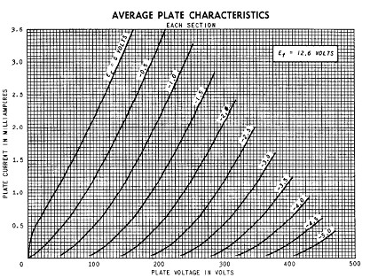
These are the curves, from m the General Electric datasheet, and most other datasheets you'll find are the same. So the following critics is not for GE only, it is for all of those faked datasheets, these are most of them. |
|
Here is a detail from the same datasheet. Look at those nice, parallel lines, with their well defined cut off points. So the lines do not point all to some vanishing point, as with real life tubes. The distance between each line is the same, regardless where you look. This means the tube has no distortion. Now with amplifying devices, distortion and gain go hand in hand. So for a tube with very high (100x) gain, some distortion is NORMAL. However, not so when looking at those GE datasheets here. Wow! they have no distortion. How did they do that? Well for drawing such curves they used a flexible ruler. That is a plastic bar, with lead inside, and you can nicely bend it in any desired shape to draw curves. Anyway, these curves show how an ideal tube must look like, but how ideal are they in real life? Lets see what I measured with the AT1000 curve tracer, and a nice collection of NOS and NEW made tubes. GENERAL IMPORTANT REMARKS ABOUT ECC83:Ever since I test NOS ECC83 and 12AX7, I find that the average of new production is not at 1.2mA as by the text book. The average is always around 1.1mA. Also for new tubes, and 1.0mA is often seen. Don't ask me why that is, but it is so with NOS and NEW tubes. This would be a problem by itself, as plate current at fixed grid voltage is no reference for anything, just the thing is, the AVARAGE must be 1.2mA, and that is not what it is. Perhaps NOS tubes are getting too old. The only tubes which seem to come out of the boxes ALL as Bogey tubes, are the SIEMENS&HALSKE TRIPLE MICA E83CC. This is the most incredible good testing tubes I have ever seen. They outdo ANY BRAND WHATSOEVER.
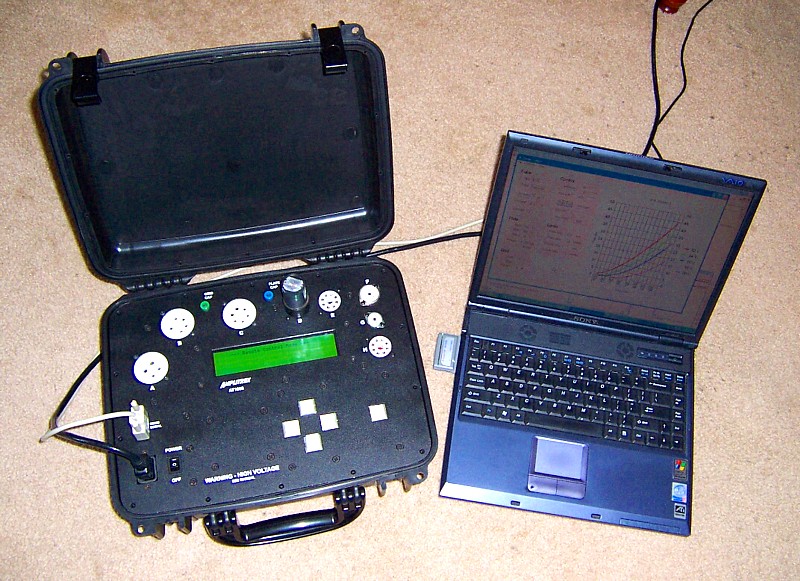
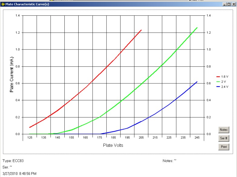
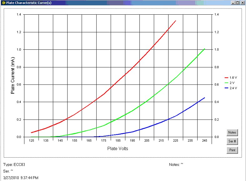
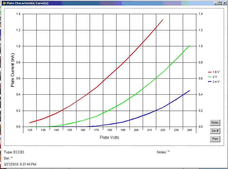
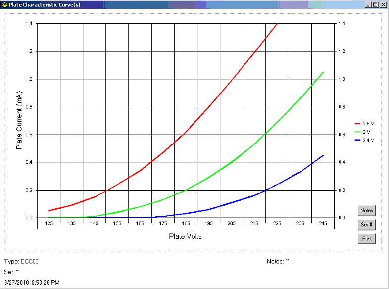
The test data was taken with the Amplitrex AT1000. This digital unit has 10 bit resolution at full scale, which is 0.1% but specially at the end of the scale resolution gets kind of "digital" so it shows "steps", which can be seen at the lower end of some curves. The low scale is 10mA, so digital steps are 0.01mA. No problem at 10mA, but it gets visible below 0.5mA of course. Also the transconductance is always ending on "00". So steps are like 1500, 1600, 1700, etc, and a tube with 1600 -1700 on both systems is in reality for instance 1641 -1692. No problem, as long as we know it. I verified the AT1000 results against the higher resolution Russian L3-3 and the AT1000 is very accurate. When you compare the graph with the test data, of course you will find the test data from the table in the curves, since it's from the same tube. The curves are made from System1 , not System2 . Look just above the number 195 at the blue line. The measured value is right above that number 195. So not at the left or the right. It's a bit unusual, but it's how the AT1000 works, the software for the graphs is a Microsoft module, called MSCHART, the Amplitrex builder told me, so that explains it.
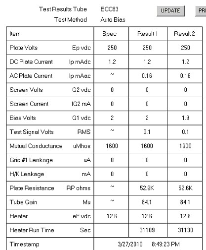
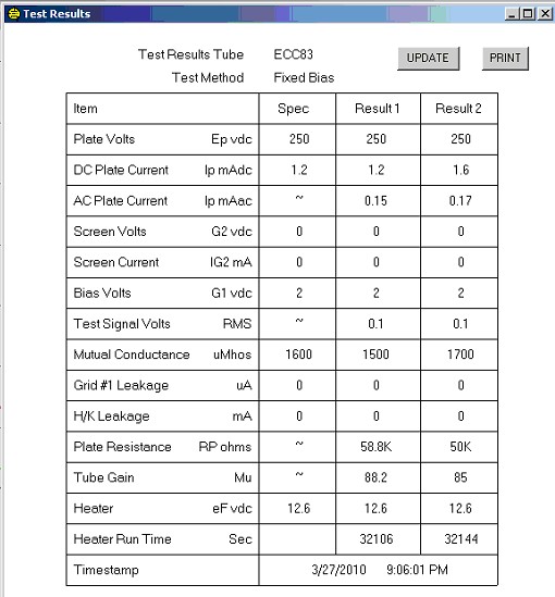
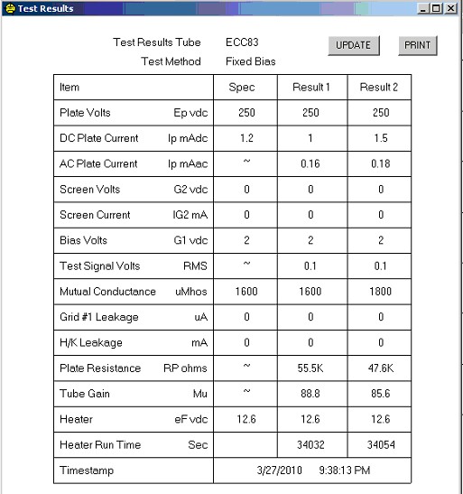
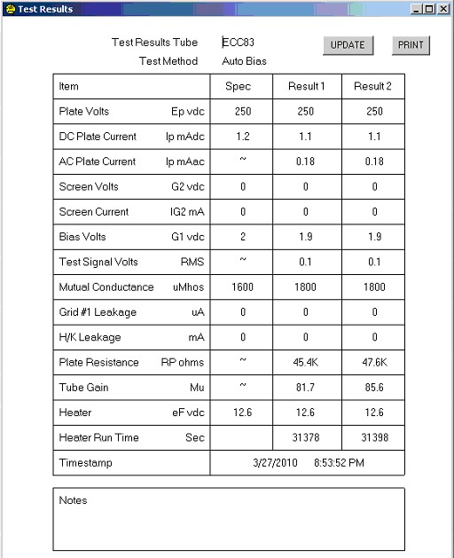
ABOUT ECC83 TEST DATA IN GENERAL:Look at the test data. The tube is set for -2Volt grid, and then at 250V plate the tube is tested So the plate current is exactly 1.2mA on both systems. This is no "Must", and in reality most tubes have a deviation of +/- 0,3mA and are fine tubes still. Also Tesla can have some deviation. The transconductance is exactly right 1.6m/V. Next thing is something O observed more often: Gain is a bit lower at around 80...85x. I don't know what that is, but I seldom find an ECC83 with a gain if 100x and when I do, it's a bit funny testing tube anyway. Plate impedance is a bit lower than average, this is normal too, and plate impedance goes up somewhat while a tube ages, and transconductance goes down. These two things together keep the gain constant while the tube ages, since gain is Rp x transconductance. So the data table is very nice TUBE CURVES Each tube curve by itself is a genetic fingerprint, meaning it holds the data for the other curves too. So we draw only tree curves, it is enough, and otherwise the plotting of all those curves would take too long.
|
|
NOW FOR THE BIG ECC83 / 12AX7 TEST: |
|
TESLA E83C
What you see here, is a reference tube. Few tubes come near to it. From what I know, only E83CC Siemens and Halske is as food. The curves are even better as the cosmetically hand-corrected General Electric curves. What do we see?
|
|
JJ-E83CC
First thing we see with the JJ is the remarkable difference between the system 1 and 2. This comes from not well adjusted tools in production, or perhaps from other reasons, but whatever the cause, the tube systems 1 and 2 are mechanically not the same. It is a matter of taste if you tolerate this. |
|
JJ-E83CCThe curves do not compare to the NOS TESLA. Note, the JJ E83CC is a mechanical copy of the TESLA E83C. So what we see here, we have a NEW production JJ, and the curves are less nice as an NOS TESLA that was unused in the box for 40 years.
|
|
Telefunken ECC83
|
|
Telefunken ECC83This is a new out of the box Telefunken, with older Type black on white box. On the bottom is a special sticker with pink ink saying 22.4.1950. I wasn't seen born then. So here comes this tube out of the box, and I put it on the Amplitrex AT1000. It shows one triode has another plate current. The difference is 0.4mA. It is as much as the JJ, which have a bit of a bad reputation for this. However, we must stay realistic, we cannot retro-define a new standard. Such deviations were normal 60 years ago, as we can see from this NOS. For the rest, this tube is pretty much average with the data. Simply good, no more and no less. The good thing of the Telefunken is the very high lifetime expectation, lowest hum and lowest noise. For more constant parameters, the TFK ECC80S is the tube, since ECC803S is defines as having maximum 15% Deviation. (Per Triode that is, so 30% between the two)
|
|
Electro Harmonix ECC83
Electro Harmonix ECC83This is a reasonable tube, but not the best for HiFi. They make this tube with slightly different data on purpose, to get a special kind of distortion, in amplifiers for electric guitar, which their chief engineer JC Morrison refereed to me as "brown sound". WIth older lots, I had vacuum problems during storage. This was not solved by EHX satisfactory.
|
|
| WILL BE CONTINUED! | |