Considerations when designing a power supply, using chokes.
It is often believed, a combination of two chokes and two capacitors works better, vs. just one choke and one capacitor, and I have to admit my initial estimation was just like that. Here is a simulation of this, showing the opposite. The total inductance and total capacitance was chosen the same of course.
Also the advantages of an LC filter is explained here, vs CLC filter.
It all begins with a good design
A good product has no compatibility issues. If followed classes on this subject at the George Washington University, but no matter if you talk about micro waves, or hum issues at 50Hz, in the end the learning effect was always the same: Designers should not let errors slip in knowingly, only being forced to solve those problems later, at much greater effort.
Power supply compatibility
I use the word compatibility on purpose, because there are always places, inside and outside, which produce hum radiation fields, and some other places which can pick this up. At a hum issue, the question is, if too much hum is produced, or if the rest is too sensitive against it. Either way is possible. Yet it works problem free as long as things are compatible with each other. Meaning some hum field radiation can be tolerated, as long as sensitive parts are protected, or are insensitive by itself.
A perfect example.
The concept of my Leslie 122 amplifier is very impressing, showing what good engineering means. Using a differential amplifier concept (called "balanced" in today's HiFi talk), makes the inputs extremely insensitive to hum. This is the weirdest amplifier design I have ever seen. By relatively simple things they do, they make the amplifier part extremely insensitive to hum, and then they can use the simplest power supply you have ever seen, and use a 10 meter long, unshielded mains cable for the signal input. The thing is DEAD silent, with 16 Inch Alnico bass speakers. Here is some more information about it.
Measuring low hum signals
At the loudspeaker terminals, audible hum begins somewhere below 2mV, depending on the loudspeaker efficiency. Users of high efficiency speakers complain already at 1mV. Some excellent multi meters are able to show single millivolts, but that's pretty much the best they can do, and it the reading is quite instable. This means any hum adjustment can not be done with such a meter, and you a milivolt meter, or a head phone. Meters which can do this, are more like instrument type, but the problem with those is, they have a mains cable, which obstructs the measurment. So you think you measure something, but it is wrong.
Only very few meters with a 1mV AC work on batteries, but such are the only useful types. The battery operation will give incredible high CMR by itself. When the inputs are chopped with FETs, you have what it takes. These are hard to find, I use an UNIGOR 6e for this, it's my favorite precision multi meter, I never found anything sensitive like it.
I also use an old HP130C oscilloscope for this, which has unbelievable good matching between the two differential inputs, and you can make 0.1mV at 50Hz nicely visible. Some scopes from Tektronix claim better resolution, but I have a few, and they all don't do as well as the HP 130C. That is because the CMR of the 130C is incredible much higher, and it is noise free. Whereas the Tektronix are too noisy to make 0.1mV visible.
A Tube filament power Supply
With a transistor amplifier, there are less power supply issues. With a tube amplifier however, impedances are generally higher, and voltage amplification is a lot higher, which makes the circuits become more sensitive for hum fields inside the chassis. So the better result is not achieved by allowing such fields to build up, and then try to build circuits which can withstand it. This may end up with impossible to cure residual hum. Such a situation is characterized by the hum not going away, no matter how large the values of the CLC filter are chosen. Even at fully excessive capacitor values, it doesn't seem to cure, which already points into another reason, as just the capacitors being not big enough.
Why you should not use a CLC filter for a low voltage power supply, inside a tube amplifier.
When experimenting with a classical C-R-C or CLC filter, by trial and error, we all grabbed capacitors from the used parts box, and we all learned quickly, the first capacitor makes the output voltage go up much better than the second capacitor will do. Whereas the second capacitor seems to do a much better job removing AC ripple. So that learning effect seems like this is the way to go. However this can be misleading.
Let's just see what happens to the poor first capacitor. We are charging and discharging it 100x or 120x per second, depending on your mains frequency. Well, you would say, isn't that was a capacitor is for? We must look at it's capacitance. We choose the capacitance high, because that seemed to work better. However charging and discharging it 100x per second, for let's say 50%, will drastically reduce it's lifetime when it's an electrolytic capacitor. There are tables for that in electrolytic capacitor data sheet, showing something which should not come as a surprise: At maximum stress, lifetime is minimum. So what is maximum stress? That is maximum AC current trough it. And what is minimum lifetime? The answer is: 2500 hours. Yes, that little! So making a design, not even measuring AC current through the first capacitor of a CLC filter can be a bad error. Don't we all have an multi meter? So put it in series with the capacitor, and use it. On the other hand, we probably want to go for maximum lifetime, and what do we see there in the data sheet: 25.000 hours at 25°C. With a derating table or a formula, for higher temperature. But you will see, the AC current to achieve this, you have exceeded it by far. This is why some older power supplies fail and some do not. I seems some designers just don't know this.
A seemingly working solution is to over size the capacitor. Like that it will not be fully charged and discharged any more, and the larger they are, the more peak current they can take, while the transformer can not supply this anyway. However using the transformer winding as a current limiter, will make the transformer hum louder, and also gives signal distortion on the high voltage outputs, which can cause other problems. Moreover, such use of the transformer makes it hum even more louder sometimes, after some years. (confirmed to me by Per Lundahl, from Lundahl Transformers)
All in all, with these kind of things, we talk about bad design. Just imagine what happens, if a HUGE capacitor has a momentary voltage of 10 Volts, and the (unloaded) transformer winding momentary value rises for instance to 15 Volts. So what makes the 5V difference go away, provided this may well be a 4 Ampere winding? Such a winding if made for 4 Ampere, is capable of peak current which is a multiple, like 10 Ampere. You have to do some math on this, but one way or another this will generate excessive current spikes, limited by the transformer peak value. So we are in the range of 10 Ampere perhaps, and the wiring of those parts become then hum radiating devices. Reason is, an electric wire with a current through it, produces a magnetic field around it. Which field, by nature, gets attracted by iron parts, but also by electrical wires, generating a voltage in those, and this is where real problems begin. So the question, if a pulsing current of 10 Ampere, can cause a voltage of 1 mV inside a near by audio circuit, give it a yes of no answer. Or do the math on it, using the rule of Lentz, for signal induction. I think it needs little explanation,what happens of you do so, which takes us to the next part:
Why an LC filter is the better choice.
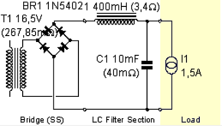
The LC filter is difficult to understand, but you can still make design with it and make no mistakes. In this respect it is the opposite of the CLC filter.
A very strange effect is, what the current through the choke will do. By definition this is always a clean DC current, because that's what chokes are for. No strangely, out of the rectifier bridge must also come a clean DC current, and not a double wave rectified AC current any more. You may think that is not possible, but it is a s fact, because what flows through the choke, can only be the same as what comes out of the rectifier bridge.
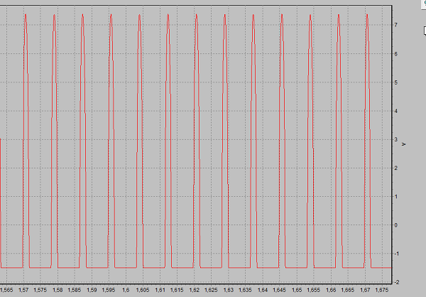
It gets even stranger, when we look at what goes inside the rectifier bridge. This is the same as what comes out of the transformer. This is a square wave as can be seen in the next picture.
The curious situation is, the transformer gives a normal sine wave voltage, but current is a square wave. Which as well could be called a DC current, of which the polarity is reversed. So, after the rectifier we have a DC current indeed. It gets even better. Do you think the diodes forward voltage, obstruct this nice square wave perhaps? No they don't! The choke simply compensates any voltage at all, by generating such a voltage, positive or negative, as needed to keep the DC current of 1.5A flowing, no matter what. It even compensates it's own internal resistance. This is the amazing property of this circuit.
Another curious property is the load regulation of the LC circuit. It's just the common word for it, but somehow there is regulation indeed. The CLC circuit reacts not very well to load changes, unloaded and loaded voltage are much further apart than with the LC circuit.
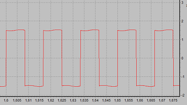
The peak value of this square wave is 1.5 Ampere, same as the filter is going to supply. So these current pulses are significantly lower as with a CLC filter. The radiation while transferring this signal through wires is low by itself, and really only present in that little piece of wiring from the transformer to the diodes. Moreover this wiring from the transformer can be twisted, and then radiation will be almost zero. After the diodes, we have already a clean DC current.
A disadvantage may seem, you need much higher AC voltage, like appr. 2x the DC voltage we get, but given the fact that AC current is smaller, energy has to come from the higher voltage. Overall Effiency is better however, because lower current makes us loose less energy, and because we generate no heat in the first capacitor, as there is none. A remaining disadvantage is the higher costs, because chokes cost simply more than capacitors. Which is the reason why professional users avoid it. So much for the word "professional", but when building top class DIY equipment, consider it.
Here is the current through Capacitor C1, as you can see it discharges with 1.5 Ampere, which is the negative value of 1.5. This is as expected. But also you can see it charges with aggressive needle pulses of 9 Ampere peak to peak value.
Sharp needle pulses of CLC circuit
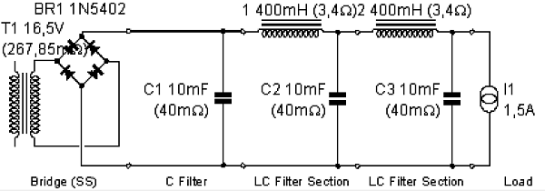
Using one or two chokes in a tube filament circuit.
For this we compare these two circuits. Note, the could was split in two smaller ones, and so was the capacitor.
One-Section LC Circuit
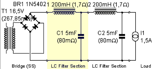
Two-Section LC circuit with same total inductance and same total capacitance
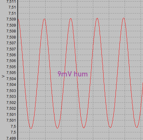
9mV peak to peak hum at the load, of 1-Choke circuit
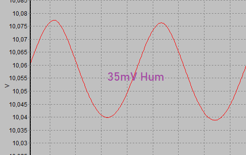
35mV peak to peak hum at the load, of 2-Choke circuit
I have to say, the result was a surprise to me, but this is how things are. So with these values, a one-coil circuit works better. This simulation program is a run time version of LT-Spice, and this makes no errors.
Using one or two chokes in a tube high voltage circuit.
It seems to work much better with two chokes, splitting the choke in two smaller, and the capacitors as well. So the total inductance stays the same, and the total capacitance also. This is in line with what I have always learned and seen.
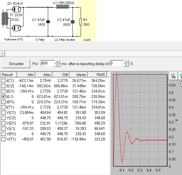
CLASSIC CLC-Circuit, first let's look at the switch on sequence.
In the schematic is used a double capacitor of 2x 47uF. Not saying this is a good thing to do, but we see people doing it. Let's see what can go wrong with this.
If things go wrong with tube rectifiers, it is sparking at switch on, or life time issues. The sparking is often blamed to the tube, because changing the tube may help. But look at it like this: If you have troubles with your partner, change to another partner may help. But what does this say about who was causing the troubles?
Let's begin with the sparking issue. I can already say, this is by definition a circuit error, unless the tube has loss of vacuum. So what circuit issues cause a spark, if the tube is good?
One possible reason for a spark is, a missing bleeder resistor across C1. Unfortunately the simulation program can not add this, so you need to take my word for it. When the bleeder resistor is forgotten, the capacitors do not fully discharge quickly after switching off. Then, at repeated switch on, this may swing up the voltage across the choke in an unlucky way, depending at what moment of the mains sine wave you switch on again. This may result in too high current through the rectifiers, at a moment when they are not fully warmed up yet, and a chip can be blasted off the cathode. This chip gets shot into dust pieces, by the electric current, even when in vacuum, and the result is the spark you see. This spark however causes a short for a very fraction of a second, and it can blow the fuse.
Another reason is the choke saturates at switch on. At that moment it stops being a choke, and what's left is a 30 Ohms resistor. Which is very low, in case C2 is still empty. It can theoretically give 30 Ampere, but of course the rectifier can't do this. All it CAN do, is produce it's "short" current. And it will. This gives a spark, and the rest of the explanation is the same as above. So will the choke saturate? Look below, the simulation program comes up with 600mA peak at switch on. The choke we uses here, is a Lundahl LL1673 10H type, which can deliver 200mA, and it saturates at 290mA. Yes, you are right, not a big distance, but that is normal with chokes. This peak is normal, it results from the empty capacitor C1, but also from a resonant effect, at switch on, which is normal.
In real life, however it does not look as bad, because the tubes while heating up load the capacitors with some delay. Yet as the moment you exceed 290mA, not matter how short, a spark may come. And please blame this on your circuit.
Use simulation programs to understand mechanism and reasons for failure, but in the end you need to measure of course on a real circuit. Like measuring the current through the choke with a current probe, or by putting a 1 Ohms resistor in series, and make a differential measurement across that resistor. And yes, things don't look too good most of the time if you check that. It's sometimes a miracle why circuits start up without problems anyway, but in case you try, a miracle is hard to force it to happen. So measure it if you can.
Spend 15 Euro on a Chinese analog multi meter from Ebay, may be a good idea. Set it a 500mA and put it in series with the choke. The analog needle tells you more than flickering numbers on a digital meter. A current probe can be low cost AC type, as long as it can do 50Hz.