Some personal information
Hello, my name is Jac van de Walle, and I was born in Holland. I've been passionate about electronics for as long as I can remember. I think I was fortunate to turn my hobby into my profession. For me, it’ is not just work, it is doing the things I would have done anyway.
I was only a few years old when I got a LEGO lamp set that I could connect to a 4.5V flat battery. It sparked my curiosity, how wires and pieces of metal would close the circuit. My father was very of my interests. When I was five years old, he gave me a box full of old switches and wires, and I’d run the battery voltage through the room, around furniture, and insert all kinds of switches and metal objects. It was so much fun, and I remember it very well.
My first real project was a Crystal Receiver which my father bought for me when I was six. We lived 20km off the coast. There were many ships at the sea, the short wave band was totally full with signals. The signals were so strong that you could hear all sorts of voices and morse beeps, by just the following in series connected: 10 meters of wire, an OA79 diode, a crystal earplug, and the water pipe in our house acting as ground. I thought I might be causing problems for the ships when I didn't switch the receiver off, so I had a bit of a limited understanding of electronics at the time. The tuning circuit was too difficult for me. When it didn’t work (which happened often), I would take it apart and start over—sometimes five or ten times—until it worked y by coincidence
The 0C13 Transistor and Nostalgic Prices
The 0C13 transistors were tricky to use because after a few bends, the lead wires would break off. But I found a way to fix them. I cracked off the glass case and re-solder a very thin copper lead directly on the chip. You might not believe it, but it worked! The 0C13 chips were fairly large, about 2x4 mm. It was clearly visible, the base was in the middle, and collector and emitter were soldered on the chip with a tiny drop of very soft metal. I could pick into it with a needle. By gently touching those spots with a fine wire, the transistor appeared working. So if I could reconnect that in some sort of a way, I thought it would work again.
I had quite a few of these 0C13 transistors with broken off wires, so I had nothing to lose. I was just a kid, and all I had was my father's soldering iron. I attached the transistor to a small piece of wood. To attach a new wire, I took a single filament from a stranded mains cable, and wound it around the tip the soldering iron. By cutting the wire to the right length, I could position it just hot enough to melt that tiny solder drop on the chip. At that age I had very sharp eyes, and I could exactly see what I was doing. That little strand of copper wire, I tin plated it first. Then, the shorter I cut it off, the warmer the tip became. I cut if off just short enough, so it would just melt that tiny solder drop on the chip. Later I learned, that drop was not solder, but it was Indium, forming the P-N Junction. I noticed it was very important, not to melt the whole drop, because then the transistor was dead. You need to melt that little copper strand just only it's surface carefuly. Once that was attached, I cut it off leaving appr 5mm. So now I had something attached to the Indium. From there, it was easy to solder a longer piece of wire to it, and voila: I had repaired the connection. Only disadvantage was, the gain of the transistor was reduced. So it worked, but it was not a good repair.
You read all these things about extreme purity, when making semiconductors. So just soldering a copper wire into it, of course damaged the purity. But.... somehow it still worked. (Experiences of an 8 year old kid...)
Interestingly, the 0C13 was actually a rejected 0C71. Philips created the 0C13 part number with lower specifications for leakage and breakdown voltage, meaning that many rejected 0C71 transistors still met the 0C13 specifications. Philips called it the "experimenter's transistor," a clever idea that made it cheap and accessible for hobbyists. The idea was that if the circuit worked with the 0C13, you could later buy the real 0C71 for even better performance. A brilliant and affordable solution for experimenters like me!
There was also the 0C14, which was a rejected 0C74. It’s interesting to note that the part numbers seemed to follow the old electron tube system. The "O" in 0C13 wasn’t the letter O, but actually a zero, traditionally used for cold cathode tubes, which didn’t need a heater voltage. The "C" signified a device with three electrodes, much like the old tubes.
Prices and Inflation Over Time:
For some perspective on prices, which I remember very well, here is how these umbers compare, adjusted for inflation of 5% per year:
-
1962: 0C13 — 2.75 Guilders → 31 Euro (2026)
-
1971: EM34 Philips tube — 90 Guilders → 658 Euro (2026)
-
1971: ECC83 Philips tube — 12 Guilders → 88 Euro (2026)
-
1968: Small new car — 4000 Guilders → 33,000 Euro (2026)
I really needed that EM34 tube for my tape recorder, but the price was steep. The shopkeeper (the one below here) told me, "Take it or leave it." The price felt like a rip-off, but I didn’t have a choice.
Back then, people often compared prices by weekly salaries, which was often payed in cash by many companies. A man from the personel department would distribute little paper envelopes, with your money inside. I remember that. An adult worker earned about 250 Guilders per week. I made 65 Guilders per week working during my school holidays. That meant I had to work seven full days to afford that EM34 tube. But I was determined to get it—I wanted it no matter the cost.
I still have that tape recorder, which brought me so much joy over the years. Unfortunately, it’s deteriorated and no longer works. But that EM34 tube is still inside, and I remember it worked as new, when I put the tape recorder aside in 1974.
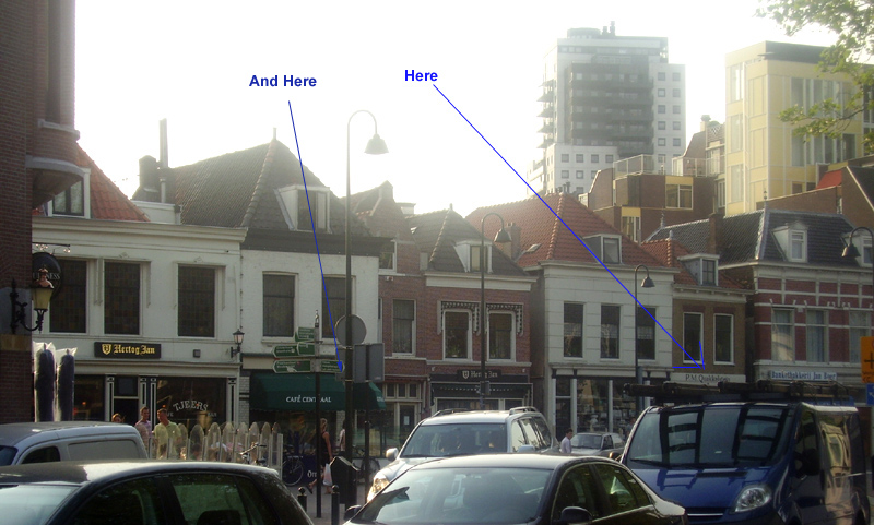
In my brith town VLAARDINGEN, I was lucky to have two very good electronics shops, 'Dirk van de Bend' and 'P.M. Quakkelstijn'. At the house of P.M. Quakkelstijn you can still see his name on the above photo. He was a tall, grumpy old man. Later his son and wife, carried on the shop until 2010 or so, and they liked their work, and DIY people a lot more. Always when I was in the area, I payed them a visit, just to say hello. Today, both shops are gone.
When I was 12 years old, color TV was coming suddenly. Each family would watch TV together from 19h to 23h in the evening, and the next morning "what was on TV" was the thing everybody talked about. So having a TV was essential. A new color TV would cost appr 1/5 of the price of a new car. So many people would use the Black and white TV until it needed a repair, and then dispose of it. Like this, I got hold of defective TV's for free.
It is a very curious observation, these old Black and white TV have extremely difficult circuits, and it should be fun to restore those today. So you would expect, DIY tube enthusiasts would be interested in those. But this is not so. You could buy them on Ebay still until the year 2010 for 25 Euro, full of "PL" series tubes. Then, as analog broadcasting was switched off around 2005 or so, you could still get analog signal via cable TV. So even if there was no TV radio transmission any more, you could still use then normally via the cable TV signal. Then, in 2016, analog TV signals were shut down permanently, and you had no more signal to watch TV. Strangely enough, these B&W TV's suddenly become "trendy" and the usual picking of the right brands and types was kicked off. Though the only way to watch TV on those, is to use an analog video recorder of the type which produces antenna signal. This gives me good hope for radio collectors, because in some years, FM broadcasting will also belong to the past. So once you can't use your FM Radio any more, those SABA and Telefunken Radios should become very expensive, by this strange logic. But I think that will happen. .
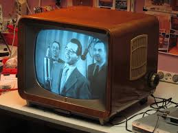 Anyway, I could get these defective TVs for free. The older Philips types without printed circuit boards were incredible build quality, with a special made 800 Ohms loudspeaker. The loudspeaker circuit worked without SE transformer directly on a PCL82 tube. Just look how amazing that worked, in order to get 800Ohms, the voice coil needs many windings, and has inductance. This inductance was used to make the tube circuit work and you need no plate choke. Such a clever design! The TV cabinet acted as an open baffle, with lots of "damping stuff" inside. The sound quality of those old Philips TV's was remarkably good, because the sound channel was actually FM. The famous "mustard" caps from Philips, people pay high prices for NOS now, these TV's were stuffed with those. They were the standard problem makers, with circuits which don't like leakage. These mustard caps are no good at all. If a circuit didn't work, and the tube itself was good, just replace the caps around the tube, gives you a 90% chance on a successful repair. These TV's had a relatively long picture tube, so they could do with not so high acceleration voltage. It was only 16kV. They suffered from cigarette smoke, as most living rooms in those days were as smoky as a gentleman's cigar club. I remember everybody was smoking like crazy. My parents, my family, really everybody, smoked like crazy. It was completely normal. These TV chassis developed a lot of heat, and so air circulation was high inside. The smoke would build a brownish layer, combined with household dust. That layer was typical in all old TVs, it was a bit sticky, and it attracted humidity, creating a smeary layer attached to all wires and plastic parts. The old timers amongst us will sure remember this. If I see a picture of such a TV, I have that "smoky" smell in my memory still, which sticked on my hands after a repair.
I still own my grandfather's 1965 Philips "Bi-Ampli" radio, with an original 'Accutronics' Reverb spiral inside, for artificial stereo. He was a heavy smoker and he "smoked" the radio in his living room for 25 years, until he died, and then the radio came to me. Even though it was not subjected to cigarette smoke any more for the next 35 years after, it still has that typical smoke smell inside. Despite that, it still works in all original condition, no repair needed ever since. I still play it frequently, which is probably the reason why it is still good. In the winter, when the atmospheric condition in Europe is humid and cold, I can receive AM stations from all over Europe, without antenna.
Those old Philips picture tubes, if good, had a very sharp picture, and were very bright too. The sharpness disappeared with the introduction of color TV, as a color signal can not appear fully sharp on a B&W TV. This is due to the chrominance "color" signal, which was later added to the the video (luminance) signal, and it would becomes visible as grey, dotted pattern, like noise.
Looking back, these Philips TV's were milestones of miniaturization, radio technique, and quality sure as well. I once succeeded re-adjusting an AM Super Radio, but it was very difficult. Re adjusting an FM tuner, I know some people can do it. But re-adjust the RF circuits of a TV? Forget it. But speaking about quality: They never needed adjustment! 99% of the problems were defective capacitors, tubes, or a broken fuse.
As a kid, I picked only the Philips versions without PCB, because the PCBs were very low quality, and difficult to re solder. Without understanding much about the details, I could repair 50% of them, and the rest served as free parts supply. A good one would sell for 65 Guilders, which was really nice money in those days. I spend it on technical books and electronics parts. When I was 15, the TV repair business dried up suddenly. It was strange how that happened by surprise, but suddenly nobody wanted to have a B&W TV anymore, and every week you could see a few of those with the garbage in the streets. Nobody including myself bothered even to pick out the tubes. (And there was a Philips ECC83 in each of them, in the channel selector... such a pity)
I finished my electronics studies in 1984 at the Rotterdam Academy of Art and Technical Science, which later merged into Rotterdam University of Applied Sciences.
I started my first job in R&D at the company 'van Berkel's Patent', now called DEKO. I was working on Analog to Digital converters and improving old power supplies. I liked bringing products with problems in good order again. I was able to give new life to a product called 834EP, an automatic meat slicer machine, controlled by microprocessor. In fact it was given up, because the motor control would blow up, and the A/D converter was instable and all kind of unexplainable defects of the power electronics. The basics design of the machine was clever made, but the electronics failed too often. Failures were a big problem, because the machine was hard to ship, and meat factories, had production problems. Meaning, service engineers had to fly over to the actual location to repair them. Very nasty for everyone. The PCB lay out was done by an older person who was outsourced, and he was doing the PCB design at home. What a mistake that was. He had zero understanding of RF problems, and his work was not recognized as the problem source. While R&D said, the circuit is good, the blame fell on the electronic parts, and the assembly company, who made the PCBs for us. So when a transistor burned out, they just replaced it one of higher quality. Like the ones with gold plated leads, and using premium brands. If that didn't work, they put in just a higher power version, etc. They even dipped the whole PCB is special resin, assuming it was a humidity problem. I found out, the real failure was just bad RF design of the PCB board itself. There was inductance and capacitive coupling everywhere. They let the 'new guy', which was me, give it a last try. It had full freedom to change the schematics and PCB as I like, because frankly, the product was given up anyway. I found many strange situations in the PCB design. It was designed on a CADET System, at those days a very good software. Only the maker of the PCBs, saw the things too simple. He mixed a design with microprocessor, with High Voltage switching electronics, and an A/D converter all on the same PCB. For him, signal mass and ground was the same. There was zero awareness for RFI problems, decoupling, good grounding, and all of those issues. You can't just have a computer program knock such a PCB together. It took me half a year to improve the PCBs, and pay more attention to the high frequency aspects of this. But after this was done, came the message from the Rotterdam production site: 'All 834EP with redesigned boards are working good, right after assembly' . They never had that situation before. It was a break through, also for myself. I was given much nicer projects, but I had set my mind already on leaving this company.
When I was already working in Germany at Hewlett Packard, my previous employer ramped up production of the 834EP very much. Recently, when I looked in the internet for this in, I saw 834EP is in production stillat the DEKO company, ever since I saved it from obsoletion in 1985. That is a production time of 40 years now! If you look at the picture, behind the red/green push buttons is the PCB.
In 1986, I moved from Holland to Germany, because of a very good job offer by Hewlett Packard. At first as an Application Engineer, and later as a field sales engineer. In those days it was a privilege to work for Hewlett Packard. At least everybody felt so, myself included. The company had a subculture, like a society. It was still original when I joined, and the founders Dave Packard and Bill Hewlett were still on duty. You would be terribly mistaken, when you think they build this company out of nothing, just by coincidence. These two founders always made rules for overall processes. With this I mean processes, which involve the whole company as such. For them, the factor 'people' was a very important one, if not the most important. In their own way, they were keeping the company on the main course, and I am sure they have put into some simple rules as well. Though such rules were of course not always openly published.
JAC-Music was founded in 1993, originally as a hobby, building 845 based SE amplifiers. Tax wise only making loss. In 1994 I got in contact with the AVVT Electron Tubes company by coincidence, and I kept in touch. In 1998 I proposed to do their worldwide distribution, and they agreed. At that time the profit was very small, and there were only three tubes in the program: 300B, 32B an 52B. For me this was just for the interest I had in it. I convinced Alesa Vaic to expand his product range, and we went through a very innovative period. We were the first to re-issue a single plate 2A3 tube, and mesh tubes, and other nice tubes like the AD1, PX4, PX25, and the 274A.
Today, you can buy a new made single plate 2A3 from several factories, but we were actually the FIRST to re-issue it. That was in the first days of the internet, and we were so happy we could gather inputs from people on the rec.audio.tubes Usenet forum, which was free at that time, and only had text mode. It may seem hard to believe, but having a website came later. We didn't know exactly how to build a 2A3, so we started with a modified 300B but we couldn't get the characteristics like a real 2A3. Later we changed the construction to get a true 2A3. This was the first single plate 2A3 build ever since the big companies stopped with it, in the 1950's.
No tube company had that tube available! Think of this while you can buy a 2A3 now from Russia, and from Yugoslavia, where did they all come from? I can tell you! In 1998, I had the first re-issue 2A3 I had on my desk made by AVVT. It looks terrible, but it works good. This tube is some piece of HiFi history! Quickly after that, we made a mesh version, with real 2A3 characteristics, and it was the first re-issued MESH 2A3 tube, that we made that way. I still have this tube, it looks very nice, and it works perfect. It's a milestone of today's Retro-Tube-Technology. This was the first mesh tube ever re-build again, and we never changed anything fundamental to the design of that tube. The initial ideas for a mesh tube came from some of our friends from the New York tube scene. (thanks Dave Slagle!) Today, there are many factories building 2A3. They are all followers of our ideas. Most of the marketing work was done by me, and the technical work was by Alesa Vaic.
A breakthrough we had, when I bought for Alesa a tube tester, of which I knew it was a bit off calibration, the reading was a tiny bit too low. They had to pass any tube by this tester, because I had exactly the same one here, but with normal calibration. Later he understood, his tester was a bit 'weak', but like that we would never have a discussion about a tube that was only 'just good' on his tester, as it would be 'fine' on my (good) tester. He accepted that.
As quality improved, business was picking up, though lifetime of the products to my opinion could have been a lot more better.
Then things went faster, sales started to rise suddenly. It was good business now. Then In 2002, unexpectedly I received a three lines email from Alesa's charming wife, telling they decided to do all sales them self. Period. In the weeks before that, she had started to fired unwanted workers in the factory too. The distributor network that I was taking care of, was send a similar email by here, saying my company was dismissed, and they can now all buy directly. Most distributors contacted me of course, to ask what was going on, but all I could say, I don't know what this is, all I received was the same information, and it is not a fake.
Then something happened, which AVVT had not expected. Some of those people that were fired, teamed up against AVVT, and they contacted me, because they wanted to produce tubes by themself, and needed somebody to take care of the sales. This was the beginning of the Emission Labs brand (short: EML). We tried to be as good competition as we could, though we had to start with little business. The first thing we did, dealers had to choose. If they sell AVVT, we won't supply EML. The Hong Kong Dealer choose for AVVT, but all the others choose for EML.
You have to understand, this was just before the internet, and before Ebay, and AVVT's main communication tool was a fax machine. I remember how slow a sales network builds up, just by postal mail or fax. The small distributors only buy something when they have an order already in their pocket. The big guys have no interest to pre-pay an almost bankrupt company larger sums. Just a few months later, AVVT had to close down.
Today, EML produces a complete line of High Power Triodes that are unique in quality and life time. Also we have re-made some original tubes as the first company. The 45 that EML re-introduced as the first o the market, was later picked up by the Chinese factories. Added to this are now some limit-breaking tubes, like the 1605, and some of our unique mesh tubes.
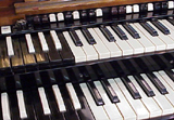
For my hobbies I have almost no time. That is keeping my Hammond Organs in good condition. I own an original B3 tone wheel organ, born in the same year as myself. It has a mechanical tone generator, and all tubes electronics inside. The B3000 I have, is a 1970's CMOS version of the B3, with the original Leslie Tone cabinets. Unfortunately I don't have the time to play them very much. Here is a sound sample of the B3.
Hammond B3 after 60 Years
Quality made in the USA. This is 70 Years old electronics. Switch it on, and it works flawless
Here is some more info about it

European Triode Festival in Langenargen 2004
From Left to the right: Jean-Hiraga, myself, a technician of Sun Audio and Mr. Uchida, owner of Sun Audio Japan. This was at the morning we left, after three days triode-fun.
My Technical background:
1984 Received my Engineering degree at the HTS in Rotterdam. Specialty: Energy, and High Voltage Electronics.
1984 ... 1986. R&D Engineer at Van Berkel's Patent, designing microprocessor hardware, and interfaces.
1985. Finished Post Academic Classes (PATO), University of Eindhoven, Holland, for Grounding and Shielding Methods.
1986 ... 1989. Application Engineer at Hewlett Packard, for Optical Communication Devices.
1987. Finished Post Academic Classes, George Washington University, for Grounding and Bonding and Shielding Methods.
1989 ... 1999. Field Sales Engineer at Hewlett Packard.
1999 ... 2001. Quality Engineer and Auditor at Agilent Medical division.
2001 ... 2003. Process Engineer at Agilent, for Optical Measurement Systems.
2003 ... Today. Working for MODC. (My Own Damn Company).
 |
|---|
A final word: Thank you for the many nice and interesting comments I received on this page :)