Since 1993 Copyright Notice
Electron Engine ™
Printed Circuit Boards by Emissionlabs
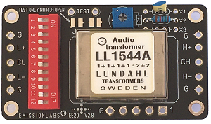
EEE20 Multi Purpose Board. Version 2.9 |
|
 |
 |
EE20 |
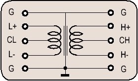
Center tap not possible if with all windings in parallel. |
Audio Board Applications - CONTENTS:
- 1. How to use EE20 as Audio Input board (NOT Phono)
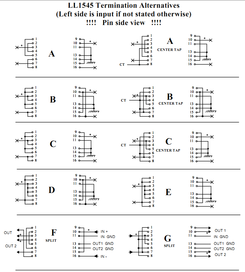
- 2. Lundahl Configurations "ALT" Method
- 3 Combine Input + Output configurations yourself
- 4 Phase Splitter Applications
- 5 RCA Unbalanced Input
- 6 RCA Balanced Input
- 7 XLR input
- 8 XLR input + balanced RCA input simultaneously
- 9 Attenuating Stage
- 10 Balanced Input with center tap
Part 1. How to use EE20 as Audio Input board? (Not moving coil)
IMPORTANT: Lundahl uses two approaches, to explain the possible options. This comes down to the same, though data sheets for this look different. These two ways are:
- Use COMPLETE CONFIGURATIONS for input and output all together. The so called "ALT" schematics. Like in the data sheets. Described in 2.1 below here. You just copy this, and it works.
- SEPARATE Input and Output schematics, which you must combine. This is for experienced users. You need to understand yourself how and why it works the way it does. EE20 can do it both ways. (SEE LUNDAHL DATA SHEET FOR THIS). Described in 2.2 below here.
- Wire it as you like, all you need to do, is using the simplified schematic, and set the gain factor.
Part 2. COMPLETE CONFIGURATIONS
This board can be used stand alone, or with the external switch. (See below)
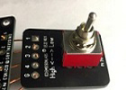
The Switch Board EE22 is optional, and allows to switch between two gain factors.
To achieve attenuation, the board is used reversed, so exchange output an input. (Section 4.5 "attenuating inputs")
This is according to the data sheet: LL1545A-ALT
Line nr |
Trans-former |
EE20 Switch Setting and Gain |
EE20 +EE22
Switch Setting and Gain |
Lundahl Alt |
Possible Use |
EE20 Board Input impedance |
Tuning options |
Line 1 |
|
1, 3, 7, 9, 11 Gain 0.5x |
7, 9, 11 Low Gain= 0,5x High Gain= 1x |
Factor 4, Impedance lowering, or attenuator. |
47k (*1) |
X1=15k. Close J2. Close J1 to activate the tuning |
|
Line 2 |
1, 3, 5, 7, 8, 11 |
5, 7, 8, 11 Low Gain = 0.75x High Gain= 1.5x |
Factor 1.8, Impedance lowering, or attenuator. |
47k (*1) |
X1=15k. Close J2. Close J1 to activate the tuning |
||
Line 3 |
2, 7, 9, 11. RCA+=L+
|
7, 9, 11 |
10k <=> 10k |
47k (*1) |
6k8 at X3, and 470pF at X2. Close J1 to activate the tuning |
||
Line 4 |
2, 7, 9, 11. Gain 1xXLR1=CL, XLR2=L+, XLR3=L1.
|
7, 9, 11 Low Gain= 0,5x High Gain= 1x |
10k <=> 10k |
47k (*1) |
6k8 at X3, and 470pF at X2.
Close J1 to activate the tuning. 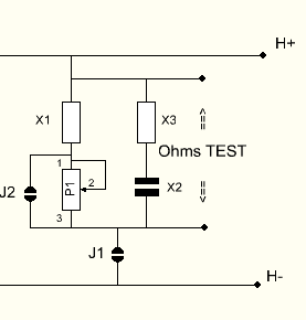 |
||
Line 5 |
2, 7, 9, 11.
Gain 1x
XLR1=CL, XLR2=L+, XLR3=L1. Out1=H+, Out2=H1,
|
Switch Board EE22 can not be used. |
Alt A. Center Tapped, for XLR or other balanced input. With SPLITTER Output, to drive Push Pull tube stage. |
10k <=> 10k *2) |
47k (*1) |
None |
|
Line 6 |
1, 3, 5, 7, 8, 10, 12 Gain 1x |
5, 7, 8, 10, 12 Low Gain= 1x High Gain= 2x |
600R <=> 600R *3) |
600R |
None |
||
Line 7 |
2, 5, 7, 8, 11 Gain 1.5x |
5,7,8,11 Low Gain = 0,75x High Gain= 1.5X |
21k (*1) |
None |
|||
Line 8 |
2,5,7,8,10,12 Gain 2x |
5, 7, 8, 10, 12 Low Gain = 1x |
Alt C Most recommended |
High Signal |
12k (*1) |
None |
|
Line 9 |
1, 3, 4, 5, 6, 8, 10, 12 Gain 2x |
4, 5, 6, 8, 10, 12 Low Gain = 2x |
Alt D Only for low impedance Source |
Normal Signal |
12k (*1) |
None |
|
Line 10 |
2, 4, 5, 6, 8, 10, 12 Gain 4x |
4, 5, 6, 8, 10, 12
Low Gain = 2x High Gain= 4x |
3k (*1) |
None |
|||
Line 11 |
1, 3, 7, 9, 11 |
7, 9, 11
Low Gain= 1x High Gain =2x |
47k (*1) |
None |
|||
Line 12 |
1, 3, 5, 7, 8, 11
Gain 1.5x |
5, 7, 8, 11
Low Gain=1.5x High Gain=1.5x |
20k (*1) |
None |
|||
Line 13 |
2, 7, 9, 11 Gain 2x |
7, 9, 11 Low Gain =1x High Gain=2x |
High Signal |
12k (*1) |
None |
||
Line 14 |
1, 3, 5, 7, 8, 10, 12 Gain 2x |
5, 7, 8, 10, 12
Low Gain= 2x High Gain= 4x |
Normal Signal |
12k (*1) |
None |
||
Line 15 |
2, 5, 7, 8, 11
Gain 3x |
5, 7, 8, 11 Low Gain=1.5x |
5k2 (*1) |
None |
|||
Line 16 |
2, 5, 7, 8, 10, 12
Gain 4x |
5, 7, 8, 10, 12
Low Gain = 2x High Gain= 4x |
High Signal |
3k (*1) |
None |
||
Line 17 |
1, 3, 4, 5, 6, 8, 10, 12 Gain 4x |
4, 5, 6, 8, 10, 12 Low Gain =4x High Gain= 8x |
Normal Signal |
3k (*1) |
None |
||
Line 18 |
2, 4, 5, 6, 8, 10, 12 Gain 8x |
4, 5, 6, 8, 10, 12 Low Gain =4x High Gain= 8x |
734 Ohms (*1) |
None |
|||
*1) Output of board loaded with 47k amplifier input. *2) This 1:1 configuration transfers high impedance 1:1. So 10k in = 10k out, or 47k in = 47k out. Etc. *3) This 1:1 configuration transfers low impedance 1:1. So 600R in = 600R out, or 1k in = 1k out. Etc. *4) trying to get gain with a high impedance splitter is not recommended. |
|||||||
Part 3. Combine Input + Output configurations yourself
This is according to the data sheet: LL1545A.
Note this:
This data sheet has only REVERSED, so ATTENUATING Applications. It means H+ and H- is the INPUT. Lundahl did it this way, we just replicate this here.
Input Applications |
|||
Line Nr. |
Scheme |
Set Switches + Connections |
Remarks |
Line 19 |
|
Set: Switch 2
Input H+, H- |
If XLR is used, connect XLR shield to chassis ground of the receiver. |
Line 20 |
|
Set: Switch 2
Input H+, H- |
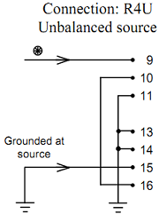
Though the source is unbalanced indeed, Lundahl uses a 'ground lifted' input.
For a normal, grounded RCA input, connect H+ to ground with a wire link. |
Line 21 |
|
Correction network is connected from H+ to H-, and can be used to generate a defined input impedance.
|
|
Output Applications |
|||
Line |
Scheme |
Set Switches |
Connections |
Line 22 |
|
4, 5, 6, 8, 10, 12 | 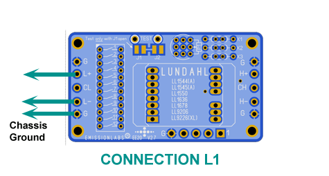
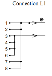
L1 = All Windings in parallelFor floating XLR, connect XLR1=G, XLR2=L+, XLR3=L1 For RCA connect L- with wire bridge to G. L+ becomes RCA out. All "G" connections are the same, at least one of them should be grounded. |
Line 23 |
|
4, 6, 9, 11 | 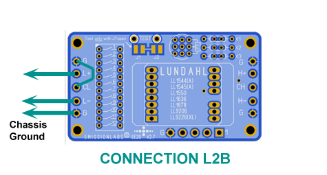
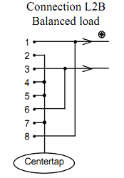
L2B = 2Windings in series
|
Line 24 |
|
7, 9, 11 | 
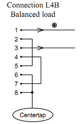
L4B = 4Windings in series
|
Part 4. Phase Splitter Applications
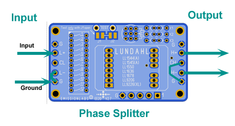 A phase splitter transformer is an ideal application when using tubes. For driving a Push Pull stage, we need perfect symmetry. Otherwise this will add distortion if the signal is higher. (Which is just the moment where we do NOT want to add distortion...)
However with two drive tubes that is hard, because it needs two identical tubes, some call that a balanced tube. Read more about it here.
Even when do do get balanced tubes, they do not age the same way. So 1000 hours later, the balanced tubes are unbalanced again. This often ends up with a symmetry potentiometer, which needs to be adjusted by oscilloscope, as the tubes age, and sure at tube exchange. This is quite an unfavorable adjustment point. Yet for cost saving it is done. A half way good solution is to use a totem pole circuit, which can work without adjustment indeed, but such a circuit has different output impedance of both outputs, is also not free of aging, and it adds some to distortion at high signal. Moreover, if done with double triodes, the different heater-cathode potential of the channels stresses the tubes very much, and you may run into hum problems, blaming the tubes for this, but in fact maximum heater-cathode voltage is exceeded, or it comes just too close. From selling tubes, we can say, a totem pole is the #1 a trouble maker for crack and pop noise, specially with E88CC, for reasons explained here.
The typical Lundahl phase splitting capable transformers have what is called symmetrical windings, so there is no inductive or capacitive difference. These are from this series: LL1544 and LL1545. LL1550 is also possible. No microphonics, no aging, no adjustment, no hum, and no noise, and more cost effective too. A pair of NOS E88CC costs more.
Note, a 1:1 phase splitter gives 2x the load on the driver tube, and a 1: 2 splitter gives even 8x the load. So gain should be used with care, and needs a low impedance drive tube. So design with 1:1 and when you driver tube can take some gain, you can set the gain of the board higher.
If used as a splitter, in forward application, there are some more considerations:
- EE22 GAIN SWITCH Board can NOT be attached. The gain is always fixed (by the Piano Switch)
- For an unsymmetrical input, any gain can be chosen, but high frequency response is best at 1:1.
- The correction network is not used, so the solder Jumpers J1 and J2 are left open.
- For a splitter with external signal source, an XLR Input may be used, with any gain you choose. This is provided the XLR signal is floating, the ground is only used for shielding, and drive impedance is low.
- A symmetrical input to ground however, which is NOT floating (Such es when connected to a PP circuit) can only be used with gain 1:1 or 1:2.
Part 5. RCA Unbalanced Input
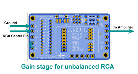
This is how to create a simple gain stage inside an amplifier. Select any ratio from 0.5x (Attenuating) to 4x (Gain), by simply set the Piano switch by the table. This is using LL1544, LL1545, which are probably the most convenient to use, because these will also ATTENUATE if needed (So gain = 0.5x) if needed.
With LL1550, Gain can be selected from 1x to 8x. Whereas input impedance becomes quite low at 8x gain, impedance will be the same as with LL1544 or LL1545, if the same gain is chosen.
Moreover, by adding the Optional EE22 Switch Board in addition, the amplifier becomes a High-Low Sensitivity input.
Part 6. RCA Balanced Input
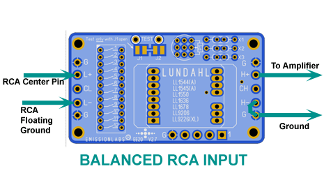 Most RCA connectors are grounded to the chassis by default. To convert this to a balanced RCA input, it should be replaced by an isolated ground type. Sometimes such an isolated ground RCA connector was already used, and it's ground was connected to the chassis with a wire piece. In that case, just cut this wire piece off. The center of the RCA cable is connected to X+. The shield is connected to X. Already now the input is balanced, even though it has RCA connectors.
Part 7. XLR input
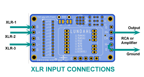 We don't want to mention names here, but some amplifiers have fake XLR inputs. This is really FAKE as can be. These are simply wired internally to an unbalanced input. So the amplifier already has all of the hardware, just the transformer was not installed. In this case, using the EE20 board is a VERY GOOD idea.
If you have a FLOATING sender, this a bit unusual, but it may be. On that case, it may be a good idea, to ground the CL connected with a wire link to G. This is only possible for switch combinations from the table, which have switch #7 is closed. (In any other combination this will not work, and cause a short, yet you will see, these are still many possibilities)
Part 8. XLR input + balanced RCA input simultaneously
This is a really interesting option, since the only investment is the extra connector! Simply wire an RCA and XLR connector simultaneously, like in the above diagrams. When done, just use either the XLR, or the RCA, as you like. What we achieve here: The RCA input will still be truly balanced! Using fully the shielded properties of these transformers. Yet it stays fully compatible to any other RCA connected amplifier, no matter if it is a balanced or unbalanced type.
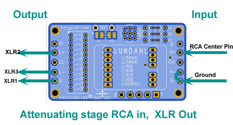
Part 9. Attenuating stage
This is advised, when the pre-amplifier has much more signal as required. Such a situation will give unwanted microphonics and other noise. Before considering an attenuating output, users often had a frustrating search for selected tubes with low noise. Better is, to step over the fixed idea, that if tubes appear microphonic, the ONLY explanation is "the tube". Of course, the problem is less with highly selected tubes, but this only indicates the pre amplifier is not well suited for unselected tubes. What can be the explanation for this?
In some cases, the power amplifier or the pre amplifier have more gain as needed. Or, even both amplifiers have too much gain. This may seem not important, because you have a volume control anyway. But, it will increase the effect of tube microphonics a lot.
The #1 misunderstanding of pre amplifier builders is always, these devices "must amplify" the signal. Which is wrong, when this ends up with too much total gain. Instead, these should lower the impedance, and if possible allow balanced inputs or outputs, and cutting the ground loop. If inputs or outputs are unbalanced, if output impedance is too high, if there is too much gain in the chain, or even these issues combined, you may have created a noise generator.
What to do against tube microphonics?
- First, the volume control has to be placed at the output of the pre amplifier. And yes, we know it is often at the input, but that is only because that was easier. A low value logarithmic potentiometer is hard to find, but they do exist. For instance from Vishay-Piher, part number T21AH-M0607-102B2020-TA. Alternatively use a custom made switched potentiometer, or a transformer coupled version. Anything like 1...2k Ohms is low enough impedance, because at lower signal, the potentiometer is tapped a lower Ohms value anyway.
- Second, there will be hum, microphonics, and noise added to the output signal, clearly related to the pre amplifier tubes. To make it worse, this microphonics is now amplified by the power amplifier. If the volume control is at the input of the pre amplifier, reducing the volume will reduce the music signal of course, but not the tube noise.
The solution:
If f the volume control is at the output of the pre amplifier, using the volume control will also reduce the noise. Even so, when the power amplifier has too much gain, which is often the case, this will amplify the noise even further. But not so, if the volume control is at the output of the pre amplifier. Since this (too high) gain will make you reduce the volume further, you will also reduce the noise accordingly. This is a second positive effect. Curiously, the extra gain of the power amplifier, is now used to reduce the noise of the pre amplifier. The effect of this is an amazing loss of microphonics. And then for a change, you do not need to select tubes any more.
- Using LL1544A / LL1545A reversed, give attenuation of 4x, 2x, 1.5x, 1x, 0.75x or 0.5x (The last two options are in fact "gain" if you use it reversed). All if this by just set the piano switch by the table.
- Using LL1550A reversed, gives attenuation of 8x. 4x, 3x, 2x, 1x.
- Note: For all attenuating applications, tuning is not required.
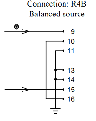
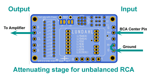 This schematic is R2U and R4U from the data sheet at the Input side. At the output side the "L" Variations can be chosen by the Piano switch. The choice between R2U and R4U is either done by the external switch board, to achieve (external) switchable attenuation, or can be done without external switch board, and set it via the Piano Switch to R2U or R4U.
Output is RCA unbalanced. This configuration has common ground. (Because both ground links are inserted).
 This schematic is R2U and R4U from the data sheet at the Input side. At the output side the "L" Variations can be chosen by the Piano switch. The choice between R2U and R4U is either done by the external switch board, to achieve (external) switchable attenuation, or can be done without external switch board, and set it via the Piano Switch to R2U or R4U.
Part 10. Balanced input with center tap.
For all those applications from the table, where switch #7 is closed ("On"), a balanced input with grounded center tap can be configured. For this, the CL connection is connected to G with a wire link. L+ and L- become the inputs. This would be useful for instance for a balanced amplifier, and LL1544/1545 is the driver transformer for the output stage. Note, this doubles the gain, because what was 0....+2Volt before, becomes now -1...0....+1Volt.
NOTES
The notes are put here, to make the above text shorter, but these things ARE important.
Balanced tubes. With two drive tubes it is hard to drive a balanced circuit. It needs two FULLY identical tubes, or you introduce distortion. If those tubes are in one bulb, some call that a balanced tube. This is of course not possible to achieve with tubes, which were not produced "unbalanced" to begin with. Just the problem is, we can not get the tubes out of the bulb, to balance them for you. This is a little bit the same story, and every time we tell it, everybody is very surprized, but no, of course not, we can not select balanced tubes from a lot of tubes which is made unbalanced. Tubes which are MADE balanced is the only type suited for this. And these are not many types, and they are always expensive, for good reasons of course. For instance E88CC (6922) is the BALANCED version of ECC88 (6DJ8). But to be balanced, they must be real NOS. New production is fake. (yes!) Meaning they write E88CC on it, and present you the data sheet of an UNBALANCED version, and sell of course unbalanced tubes as well. To make it crazier as it already is, they charge you to select "so called "balances tubes out of such a lot, which doesn't contain such.