Complete Restoration of Funke W19 Tube Tester
Everybody who is working with more than one tube tester, will probably have noticed that they do not show the same results. So I decided to restore my tube testers one by one. (Good intentions)
About the W19S
This is amongst the finest tube testers I know. It has several advantages you will hardly find with other testers. I will briefly list them here, these are as far as I know, but I may find some more later.
- It is suited for military use. This is a good thing, and I prefer it. This means it was intended for people who don't care about the value the goods, transport it like old potatoes, and only use their brain to save their own ass. The tester you are going to buy was made to survive this.
- Has all modern tube sockets, even miniature, but also very old socket types.. So it will test almost any USA and European tube. This is very important for collectors, so at Funke they did not happily obsolete all old tube sockets, as Hickok liked to do, to keep their testers simple. You will learn to like this, when some day you want to test some crazy tubes, and... of course you Funke can test them, and of course your 900$ Hickok TV7 cannot, and your 2000 Euro Neuberger RPG375 cannot, etc.
- Has an amazing complete tube manual. It refers an unbelievable quantity of tubes, and it seems there is a card for every tube ever made. Frankly I use the book sometimes when I want to find out what kind of curious tube I found somewhere, and most of the time the book will tell me indeed what card to use.
- Needs no settings. All is done by the test card. Just plug in the card, read the meter, and still get precise results.
- It is the largest and final model Funke made by the above principle. More than 35 year of evolution lay ahead of it.
- Will do a wide range of leakage tests, including vacuum test.
- Can test up to 50 Watt dissipation, and 250mA .
- Has stabilized voltages, needs no calibration, no warm up.
- Has a Headphone output with SE transformer, to test Audio tubes for noise.
- Shows when a tube is good or bad, and the best of it. In the manual is explained how this is done.
- It has the SEPTAR socket of the 6C33 tube, but not the connections for it. When you don't want to test other Septar tubes, you can modify the connections for 6C33. You need to add a heavier 6.3 Volts transformer inside, and make your own cards. For the rest the tester can do it. I recommend the testing principle used for the AD1. Like this you can make a card for max 250mA plate current. That should suit a 6C33.
- To say it again, this tester can actually test at 250mA plate current, but it can also very fine and accurate work on a 1mA tube.
- For the above reasons, Funke W19 results are worldwide accepted, and not without reason it was the standard tester for the German army and German Post ever since 1930 until ( I think...) TODAY. My tester was last time serviced by the army in 1998. Since there is nothing to calibrate, it said "comparative measurement done" on the calibration sticker. Dated 1998. Since it was build in 1965 they used it for 33 years!
Test cards. Messsage from the department of mistakes and errorz department.
I read in the internet, that some of the test cards have mistakes. Don't worry, all testers have errors in the tube data. With W19 I never believed it until I found one myself. I will list the corrected cards here. So please send me those if you have some!
Card 304. Now, this is a disappointment. This is no mistake, it is a piece of sh... and a big one. Obviously Funke never tested this card, or they would have found this stupid error immediately. Also we learn from this a yes/no answer to this question: Are all cards tested? The answer is: No. Though I have to hold against this, finding errors is rare.
Note the RES1664d is a military tube from the 1940. You know what means? I draw two conclusions from that.
- The German army never tested their 1664d tubes, because with this card it's impossible. I wonder how they tried to win the war like this.
- Funke only calculated the data on this card, never verified it with a real tube if their calculations were right. If they only tried, they would have noticed the missing hole, AND the short circuit that comes if you put a pin in a WRONG punched hole that I closed. Interesting it works fine now, with corrected holes. So they calculated it correct, but the conclusion is, other cards that you may use and think are good, may be in fact only calculated and never verified with a real tube as well. The proof for this way of working is found in card. Look here is the result: Card 304
Anyway the database they use is still a reference.
The restoration:
The principle of restoration tube electronics is simple. You need to decide where to put your focus on. Is your main concern is originality, or is it getting a precise function with best reliability? For me it was the last.
Suppose you have a radio from 1922, it would be no good idea to take out the old capacitors, and replace them by modern ones. For the function that is certainly better, but not for a collector. The collectors's challenge is to repair the old capacitors the original way, or sometimes don't repair it at all. Leave it all rusty as is, and just look at it, and imagine all the years this equipment has seen. Like something coming out of a tie capsule. Some very old radios are worth more unrestored but complete, than in restored condition. The original historical tubes, have more value than new replacements, even though the new tubes perhaps work better. So originality comes first with collector's instruments.
However, with an instrument, that you intend to restore for daily use, the story is a different one! We want to USE this piece. For an old, high quality tube tester there is no new replacement on the market. So you need to restore an old tester to get a "like new" one. The focus is going to be on using precise and reliable components, and if something new made in improvement, I use it. So here it is like this:
- Capacitors and low quality resistors will be replaced
- Replace electrolytic capacitors by foil capacitors when possible
- Tubes that test not "like new" are replaced by NOS ones
- Power resistors with special values can be re-calibrated by putting resistors in parallel. The value of old resistors only go up over time. So if the value went up just very little, and it's just a tolerance issue now, I leave the old resistor in, and adjust the value with a parallel resistor. So like a 5% resistor is now 6% off after 50 years, I do it that way. However, when a 5% resistor is 10% off, I rather replace it.
- Analog panel meter:
- Re-calibrate for full scale
- Re-calibrate for linearity. This is VERY difficult, don't do it with your Funke meter, when you need to learn it first. Needle must be re-balanced, so it will read correct in all positions.
- Remove magnetics dust particles from the magnet / Coil.
- Re-seal the glass. Otherwise new magnetic dust comes in.
- Clean all switch contacts.
- Rotary switches must run smooth and silent.
- Switches may have no leakage, or tube leakage can not be measured correct.
- Re-calibrate the panel instrument. (Here: only the analog instrument and the power resistors)
- Repair the case if necessary, replace cracked cable
- Re-solder each and every solder joint. Even if you don't "see" why. As you can often definitely not see bad solder connections in old equipment.
Some notes about old solder joints.
If you do find a bad joint, you should take the opportunity to investigate this phenomena. If a solder joint is obviously bad, like when you wiggle the wire, and you see the panel meter react, well then you found one. Now the observation will be, re-flow the solder may not solve the problem. Better is remove such a wire from the solder joint, you may find inside the solder drop, the wire has oxided badly. So just re-tip this with a hot solder iron will not help much. Even so, when you try to put fresh solder on the wire, it will not work well. This can be really a bad layer of some brown-reddish stuff, and you need to scrape it off with a knife. I found that is often so with resistors, not capacitors. Note, there is electrical current flowing through a joint, so once it begins to get bad, some electrolysis process may cause this. Electrolysis will mainly take place in DC current. So that is why capacitors seem not affected, and that is why high power resistors are more affected than low power resistors. I do not know this for sure, but I think so. What ever starts this, sure is once it begins, it gets worse. A fact is, solder joints are always crystallized, and I think this a possible beginning. A higher lead content, I made some experiments with, this gives larger crystals, and optically not nice looking surface. If the tin contents is higher, the joints look more shiny. Many don't know this, but the crystallization process continues with the years, it is always there. It cannot be stopped, and it gets worse. with humid storage. So take very good note, when the apparatus is fungus smelling, this is a sign of humid storage. Specially if there is mechanical tension on some wire, this speeds up crystallization, and they get loose or develop contact resistance. So you must re-solder it completely. Here is what may convince you: Take an old light bulb, of the kind with a solder connection in the middle. The bulb is screwed into the lamp, and there is some mechanical pressure on the solder joint of course. Look at the deep imprint this gives after some years. This demonstrates best way, that a solder joint can absolutely not be loaded with mechanical force for many years, like 50 years or so. Also not with a very small force. Add to this that some solder flux create oxide after 50 years, even attacking the copper wires. This seems not the case with Funke, but I have one Neuberger here, which has this problem. Since most of the time you cannot recognize a bad solder joint, resolder them all, is the only right thing to do.
A tube tester from Ebay, here we go again
So with this repair list in mind, I bought my W19 on Ebay. So the only requirement was that is was "working and complete". When I bought it, it was supposed to be "very good" an "like new", and I paid 670 Euro for it, from a surplus company in 2003. You don't get them for this price anymore. Of course it was full of problems. Not the kind you would notice right away. After receiving it, I checked all functions, and many worked unsatisfactory and some not at all. The rotary switch had problems, and it seems a "clever" person tried to fix it by randomly bending on the contacts. It turned out it was only "working and complete", and not more than that. Well at least I knew now, why the seller disposed of the tube tester. Since I knew where to start the repair, this encouraged me to keep it. After a short email with the seller, he admitted he only put in a rectifier, and test it quickly, and that was it. I think he really was only the seller. He offered me 130 Euro back, and I agreed. So the decision was quickly made, I kept it, and it was to be taken apart COMPLETELY.
Now the problem with taking it apart is, that they must have thought at FUNKE this would never be necessary. So the whole stuff is soldered in there permanently and you cannot get the electronics out in one piece. You have to separate the deck part from the case part. What makes it worse, the case is used to hold everything together. Arrrgggh! It is really a crazy job, repairing a W19.
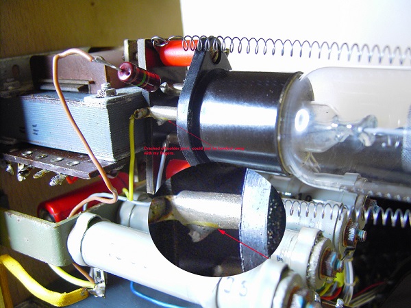
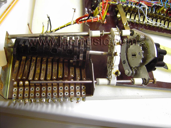
So what to do... I took about 50 detailed pictures first, and with those in my PC, I felt confident to solder the whole wire tree off. Don't think the tree is nicely organized. Some wires are going underneath here, and some other underneath there... Well, I wanted to re-solder every joint anyway. And guess what.... three solder joints I found were bad. I could just pull out the wire! They must have had contact still, but I could just simply pull the wire out! On the stabilizer tube socket, one contact was so cracked, it was almost broken off. This was a construction error. Hard to describe here, but they way they did that, I can only say: Of course this brakes off after many years. It's shown in the third picture. <== I would recommend all W19 owners to check this point.
Here is how I received it. Nice on a first look, but full of hidden small defects, as we will see later. You can enlarge most pictures by clicking on them.
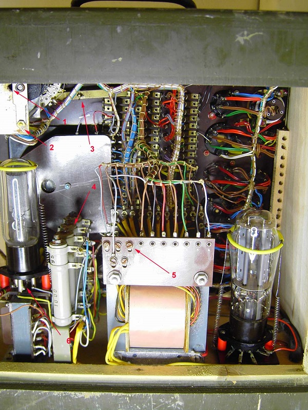
1) Bearing of rotary switch not original, and 2mm play
2) Rusty nuts, were not tight enough, but too rusty to adjust.
3) Rotary switch locking pin works not correct.
4) Ceramic Isolation of resistors covered with rust layer.
5) Rusty screws. No problem, but not nice
6) Cracked solder joint on regulator tube.
Click this image, to enlarge!
Enlarge, and look at the transformer screws.. bad... bad... !
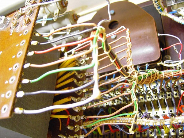
I made dozens of pictures like this, to be sure I have all details for building it up again
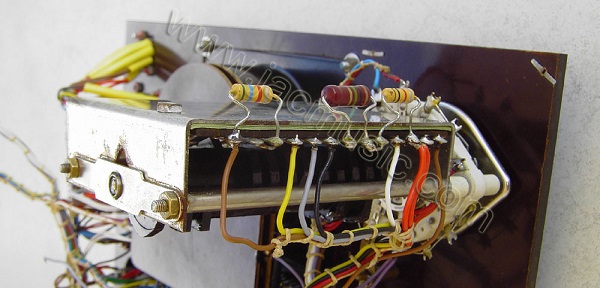
Click this image, to enlarge!
Enlarge, and look at the bad solder joint. This happened form putting in and out the rectifier tube. This may have troubled the technicians at the army!
The original electrolytic capacitor was still good. Though some white stuff had leaked out, it was still ok on a capacitor tester, even with 160V bias. No electrical leakage. Anyway, after 40 years of use, it was taken out. I replaced it by a Mundorf foil capacitor. It had the same dimensions.
After removing the deck plate, this stayed inside.
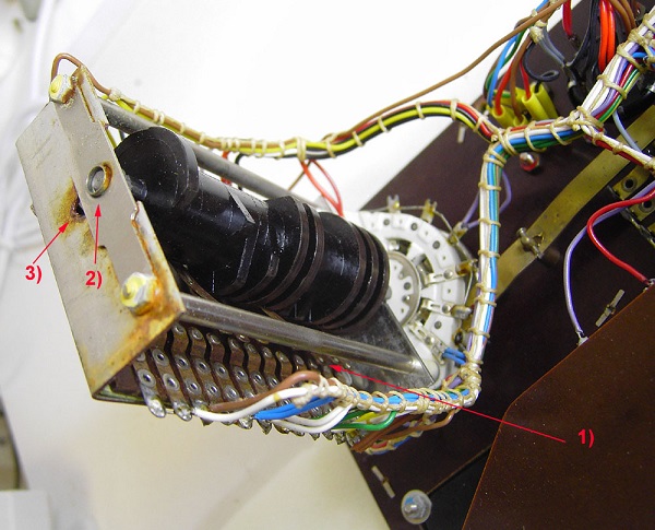
1) This contact is supposed to be closed in this switch position
2) Bearing has 2mm play
3) what's this V- shaped rusty hole for?
The switch bearing is probably not original. It had 2mm play, and most contacts were not closing reliable. The previous technician must have had lots of trouble with it, because all contacts were bend upside to correct this, but this switch is so complicated, that doesn't work well. Thesis was a monkey repair. I am SURE this is why this FUNKE W19 was sold on Ebay.
So here we go and take the whole mess apart. Enlarge the image and you will see how badly the fingers have been bend. I think with the results nobody was happy.

What a mess!
Here you see the restored switch. It runs smooth and makes a nice sound. It feels like a very high quality switch again now. All contacts were polished. The not original bearing was adjusted better, and now there is no axis play anymore.
From this picture you can see that needle is unbalanced. When horizontal it is at zero. Now... theoretically you can work with an unbalanced needle, as long as the meter is fully horizontal. Since the Funke W19 has the meter mounted under an angle of some degrees, you will get an unlinearity of the scale. I measured it is 8% in the middle of the scale. At 45mA tube will read 49mA. I think this may be an original inaccuracy, but when doing a precision re calibrating job, this is now unacceptable and must be fixed.

CLICK THE ABOVE IMAGE FOR FULL DETAIL OF THE METER BALANCING
Meter before repair. The meter is a calibrated multi meter, with solder tag connections for all voltage and current ranges. What looked like dirty mounting of the calibration resistors, was in fact the calibration itself. I noticed that Funke changed the values of the resistors by crushing them gently (creating short circuited windings), or pulling them again, removing the short circuited windings again. More about this later. Look on full detail picture here, you can see it better.
So now, after the mechanics are calibrated, we can do the electronics. First I took out the little window in the middle, polished it again, and glued it back in without any option for dirt to get inside. That was not so well done originally and dirt particles were on the meter scale. It was some improvisation finding the right values from standard resistors, but I found them. With those the full scale for the voltage measurement was re-calibrated. The Current measurement needed only two very small corrections. These are the two green resistors I put in. There is one on the top, just in the middle. Try to find the second one yourself ; ) It is on the picture. So far for the full scale calibration. As a reference I used my Agilent digital equipment.
The meter is based on a 250uA full scale meter, and with an interesting array of resistors they make it either a volt meter, or ampere meter, each with several scales. What I would like to mention here, is how the original calibration was (obviously) done. They first put in the wire wound resistors, and had an interesting way to change their values. For making the value smaller they just pressed on a small part the wound coil, so some windings get short circuited. Of course when going to far, you could reverse it by pulling the coil slowly. So in a way these coils were used as adjustable resistors. When it was done, they coils were encapsulated with some kind of resin. I don't know exactly what material that is, but it appeared to be in fine condition still, no cracks or anything. So the resistors that were still ok, probably will stay good longer than I will live. That are the series resistors of the voltmeter. The shunt resistors for the ampere meter were made of few windings thick wire. They just files off some thin pieces to make their value larger. To me it looked like damage at first, but under the microscope you could see it was done intentionally. So what looked like messy work, when opening this meter, was in fact the original calibration work, and no mess at all.
The meter on the right was used for the calibration of the Funke W19 meter. It give 6 digits, and it is officially calibrated by the Agilent calibration service. So that one is my reference. The one on the left is uncalibrated, but you it is a pretty expensive one also. These are available with calibration certificate too, but I don't have one. It shows 0.1% deviation from the calibrated Agilent meter, as you can see. So it is fine for me, without calibration. Both meters are only three years old.
Note, the analog meter you see, is on 250Volts (Lower scale). This is the from Fluke power supply, that I used to generate the test voltage.
Here is the finished W19, in the sunshine of 2005, and ready to be re-born.
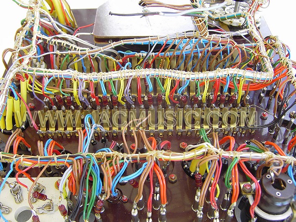
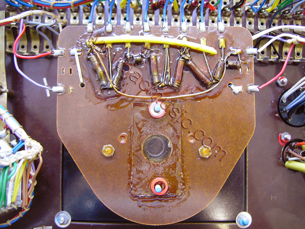
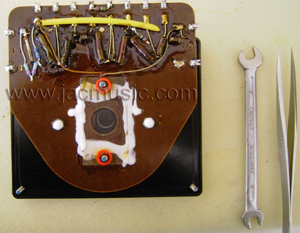
After cleaning, the bottom looks like this. Note that all high impedance connections have a 100 Ohms resistor in series with it, which is not on the circuit diagram. Any monkey mistake will blow out the resistors, and save the transformer that way. The resistors will also prevent oscillations with power pentodes, and protect against short circuited tubes as well.
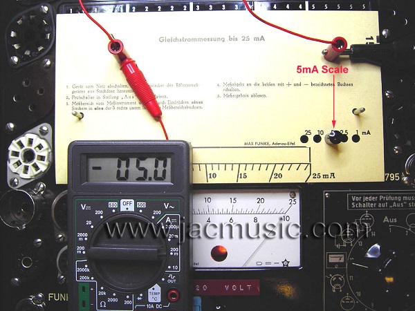
Here you see a measurement with the finished Funke W19. You need to check the full scale, and the linearity at all voltages and currents. There are special test cards for that, added to the card set. What you see here is the nice result of the 5mA current calibration. This is under the small angle of the deck plate. So linearity is fine also. This took a lot a sweat and tears, but it's perfect now. These tests need to be repeated for all scales, and then the tester is fully calibrated.
NOW THIS W19s IS AN INSTRUMENT :)
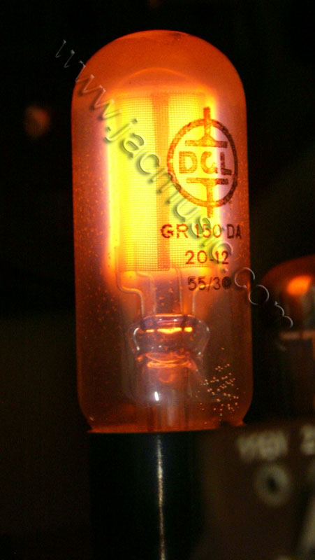
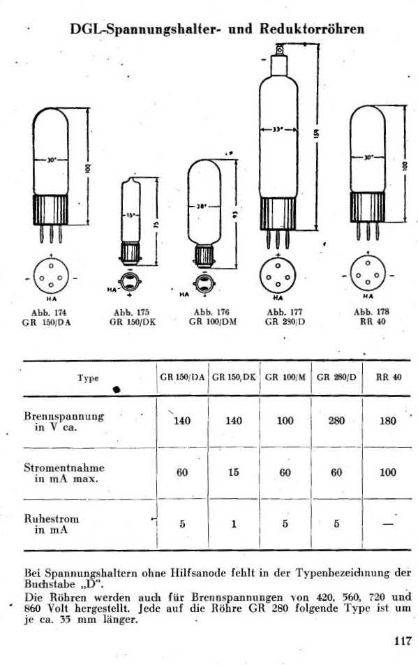
150 Volt Stabilizer tube GR150DA, used in Funke W19
Some things about the GR150DA
This is a stabilizer tube, not a reference tube. Both are gas filled tubes, and they appear the same. A reference tube though, such as OB2, you should use at as specified current window (from xx , until xx) , and then it will give an amazingly stabile voltage. Much better than a Zener diode will do. However, the load characteristic of a reference tube is not nice. So when want to vary the current through the tube very much, it will give some voltage variation, and thermal stability is not so nice also.
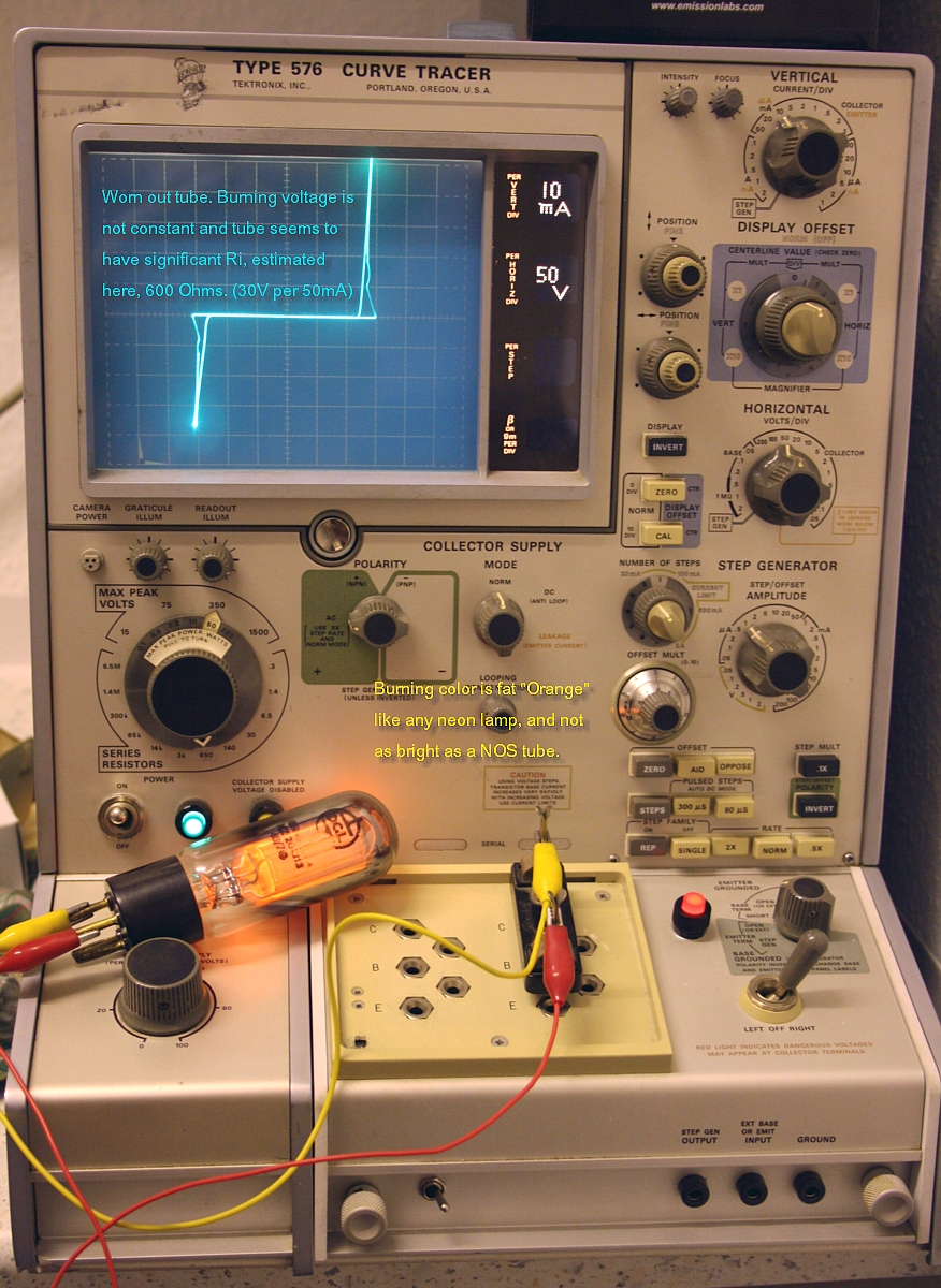
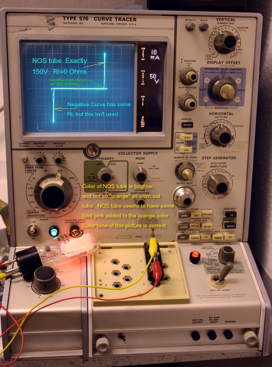
For getting good regulation, so having a constant voltage over a RANGE of current, a good thermal stability, stabilizer tube works much better. Such a tube is the OD3. A much better one is the GR150DA. There are also other types of GR150, from the same company, but for FUNKE they had a series of SELECTED tubes, the "DA" Series. I don't know exactly what they selected, and any specs were never published. Well I don't need to know either, I just use a real GR150DA and I am safe. So by all means this is the one you need. There is no replacement for this tube, since any imperfections, such as load regulation effects, are already included in the scale of the cards. This is pretty obvious of course, but it does mean a precision 150V electronic replacement, will give wrong readings. Same when you use an OD3 which is 150V also, or any of the other "so called" replacements, with just not the same load characteristic. Next specialty of the GR150DA is the ignition electrode, allowing a wider use range. Then, the GR150DA at very high plate load of the tube under test, will start to burn dimmer. Since it is also used as a control lamp, inside the meter, this is a very nice indication of the current drawn. So when it is almost off, you are close to overloading the tester. Having this indication is only possible with a good working GR150DA. So my strongest recommendation is, get yourself a NEW GR150DA, and use the one you have as a spare. So if you have a vacuum loss, or any problem with the tube you are using, you are not stuck with a useless tester. This tube is very rare! So don't underestimate this. They can be found still for instance here.
Seen on Ebay Oct 17th 2007.