Operating Characteristics of different connections of the Pentode
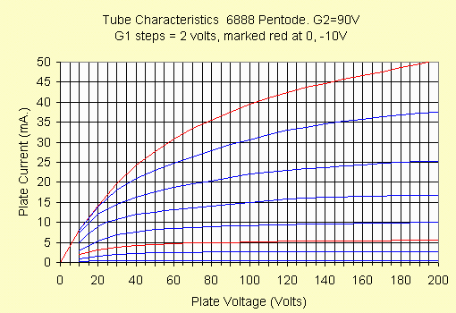
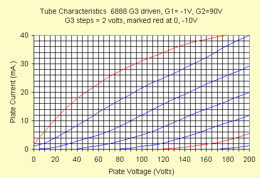
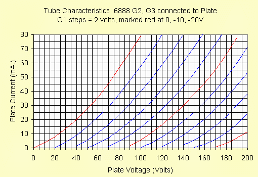
This report provides typical tube characteristics using different Pentode connections. This will be done by showing the resulting plate characteristic curves of these different connections. Standard Pentode connection (g1 as stepped parameter, g2 at a constant voltage, and plate voltage and current plotted for the stepped input), triode connection (g2, g3 connected to the plate) and suppressor input triode mode (g1=0V, g2 at a constant voltage, g3 as the stepped (input) parameter) are presented. A 6888 device is used as the example.
Pentode mode
This presents a relatively high impedance (constant current) output impedance. The relatively sharp knee at "0V grid bias" provides relatively high available power output for a given plate supply voltage. Note, however, that the knee of this "true pentode" is not as sharp as a beam power tube is, though. There is also a 100 ohm screen grid "stopper" resistor in series with the 90V source. This also contributes to softening of the knee just a bit.

G3 driven
In a true pentode (as opposed to a beam power tube), depending on the construction, it is sometimes practical to use the suppressor grid as the signal input. This provides triode like characteristics as there are no intervening control structures between it and the plate. The MU of the resulting triode like device is high. Sometimes this connection, because of the relatively high MU allows a reasonable power with good sensitivity. In the curve below, the tube is configured with g1 grounded (0 volts) and the screen at a constant 90VDC. The 6888 is particularly well suited to this application, being a "dual control" device. Notice the maximum available current is similar to that of the pentode connection, but the zero bias point is slightly lower. G1 was grounded via a 10k resistor, and this provides slightly less than 1 volt negative bias to G1, due to the "contact bias". If this point were hard grounded, the "zero bias" line (top red) would be identical to that of the pentode mode connection., and the other curves would shift up slightly. Note the MU is 35-40. One additional item of interest is the fact that some current is available at "zero plate volts", due to the G2 acceleration. Like the pentode mode, there is a 100 ohm screen stopper series resistor.

Triode mode
In this connection, g2 and g3 are connected to the plate, and the device is operated as a triode. For this connection, the MU is generally fairly low, and the corresponding plate resistance is relatively low as well. This particular "pentode" (6888) is amazingly linear in this mode of operation. Note the low MU (about 8), and rp below 1k ohm. Also note that the 90 volt zero bias point is higher than the 90 volt plate, 90 volt screen point of the pentode connection. This is due to the use of the screen stopper in the pentode and g3 driven case and the fact that the screen in those two modes does not contribute to the overall "plate" current as it does in triode mode.

There are other connections possible with a pentode, three of which are reasonably popular. One of these is "ultra linear", generally done by way of a tap on the transformer. In this connection, the voltage on g2 is some portion of the plate voltage. The characteristics are intermediate between triode and pentode connection.
The second sometimes used connection is "enhanced triode" connection. In this connection, the input is on G2, generally between 0 and near the plate voltage. The power gain of this connection is low, since G2 consumes current, as it is forward biased.
The third connection is space charge grid connection. Here g1 has some fixed positive bias, the input is a negatively biased g2, acting as the control grid, and g3 connected to plate. This allows a very high relative current as electrons are pulled from the cathode by the nearest available structure. Unfortunately, this is also fairly wasteful of cathode current, and not very linear.
Expansion on these items may become another article.
Steve