Document Revision History
Rev 1.0 Jul 11 1999 Initial Presentation.
Rev 2.0 Jul 31 1999 Rearranged document to provide better detail as various "objectives" are met. This revision includes three updates: links the DHT hum reduction information presented previously on these pages, details the input/driver stage, and describes a modification to the input/driver stage to make a 1/2 watt DHT SE amp. This was also auditioned sonically.by a group of about 10 people.
Rev 3.0 Aug 27 1999 Tests with the 6AS7 "final" have been incorporated. List of available schematics have been included. Specifications have been placed in a table for ease of referral.
Rev 4.0 Sep 21 1999 Details the results of the second sonic audition.
Rev 5.0 Oct 31 1999 Details the results of the third sonic audition.
Objectives
Background / Topology
I've done a couple of reports on using triodes in inverted mode as a way of achieving very low plate resistance. The latest report can be viewed here. By using several paralleled 6080/6AS7, the plate resistance is low enough so that neither feedback, nor output transformer is needed to achieve good damping and direct coupling.
This requires somewhere about 100VRMS drive, so for a sensitivity of about 1VRMS, a input/drive stage of about 40dB is needed. One possible configuration is 6SL7 driving a 6B4. Another is 6SN7 driving a 10 or 801. Another is 841 driving an 801. There are many other possibilities using smaller devices, as well as possibilities using the Svet 6BM8 as well as other tube combinations. However, after trying several combinations, the 6SN7 driving a 801 seemed to produce the results I was initially looking for. The input and driver stage report can be obtained by clicking here.
Power supply for the driver is 0A2 regulated. I'm using +300 volts on the 6SN7 with its cathode directly grounded, and fixed biased at about -2.5 volts.
The output stage power is also "split", although, due to the high current, each channel has its own regulator, currently running +48 x 2 and -25 x 2 (with adjustment pots). The regulators are also bypassed with 10,000uF, and 10uF poly caps. The 6080s are biased from voltage division between -300V and -25V to provide the tube bias. (With adjustment pot).
All power supplies are currently "linear". One of the goals of this project is to evaluate the effects of switch mode supply.
The input stage / driver, the output stage, the low voltage power supplies and the high voltage power supplies are all built on separate chassis, so that they can easily be changed for comparison/evaluation purposes.
Current Results
The following table represents the currently achieved specifications. This will change during the various investigations and represents "current" results.
| Power Output no Clip | 2+ watts |
| Frequency Response (1 dB out of clip) | 5Hz-120kHz +0-1dB |
| S/N referred to power output value | 85 dB |
| Output Resistance | 3.46 ohms |
| Sensitivity for 1 watt | 0.45VRMS |
| Second Order Distortion at 2W | 1.5% see third audition results |
| Third Order Distortion at 2W | 0.8% |
| Second Order Distortion at 1W | 1.3% |
| Third Order Distortion at 1W | 0.05% |
| Second Order Distortion at 100mW | 0.6% |
| Third Order Distortion at 100 mW | 0.005% |
| Weight | 48 pounds |
| Power Consumption | 560 watts |
Additional Reports on the amp:
1. Hum Balancing. Can be read by clicking here.
2. Input and Driver Stage: Can be read by clicking here.
3. Output Stage: Can be read by clicking here.
Schematics available (by EMailing your request)
1. Input/Driver Stage
1a. Input/Driver stage with distortion compensation
2. Output stage and power sequencing circuitry
3. High Voltage power supply
4. Low Voltage power supply
What's it sound like?
The added sound level provides a more responsive amplifier than just the driver stage. The sound is almost as delicate as the driver alone was. The amplifier sounds very good now. It's well balanced, dynamic and clear. This is attributed to the different bias conditions set up. The bandwidth of this amplifier is very impressive. The bass is very well controlled and very distinct. Very high frequency is clean as well. The performance going into clip is also much better with the lower voltage and higher current bias point chosen. The distortion cancellation added for the third sonic audition was a success as described below.
Second Sonic Audition
A second sonic audition was held. For this audition the OTL bank of 6 tubes per channel was used, and an A-B comparison was made that altered the bias on the first stage from its normal bias to about -0.5 volts. This has the effect of causing the composite amplifier to have less overall distortion (2%), but the remaining distortion is a mixture of 2nd, 3rd and 4th orders in decending amplitude, rather than 4.9% mostly all second order. The gain was pre-adjusted to produce about the same level in either position (within about 0.5dB).
The results were very interesting. Almost everyone preferred the higher distortion but only second order distortion for all musical selections except for "rock". Comments were "more forward", better imaging, better detail for the amp. The frequency response was great at both ends of the spectrum. Interestingly, the higher second order distortion selection seemed LOUDER; universal comments: are you sure there's only a half dB difference? The A-B change was not very subtle in its sonic difference!
The overall results: pretty good overall. The group "recalled" a sweeter more delicate first audition (driver only), but the amplifier with the "finals" running definitely had much more authority. Clip point was still relatively hard to pick out (which is common for SE amplifiers), and the overall amp was judged very good. With a bit less overall distortion this would become a great amplifier.
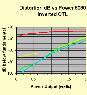
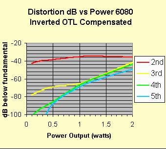
Third Sonic Audition
For the third audition, a different form of distortion cancellation was tried. Again this was presented in the form of an A-B comparison. The gain difference between A and B was about 0.2dB. There was no substantial difference in frequency response or noise. The sonic qualities of the distortion cancellation mechanism were the objective of this phase. This type of correction lowered ALL the harmonics present. This was accomplished by adding a 6SL7 not directly in the signal path but in series with the 6080 bias circuitry. Here's the distortion data for the test.
Distortion characteristics of the amplifier:
The effect was more subtle than the audition 2 test, even though there was more of a difference in the overall distortion. One person was easily able to hear the difference, however, at all levels. The team unanimously preferred the compensated version. Clearer, more focused. Better sound stage. Judged slightly brighter as well, although there was no difference in frequency response. Also received comments of better resolution in the low-mid frequency range.
What was achieved is the added power and better response (due to the OTL) combined with the delicacy and finesse found in the during the first audition of the driver only stage. Also the de-focusing effect of multiple paralleled tubes seems to have been corrected as well.
This also indicates is that under certain conditions, distortion correction mechanisms can be used, and their use has no adverse side effects. The key here seems to be to insure that all harmonics are reduced by the cancellation mechanism; not merely re-distributed. The only way this seems to be currently achievable is to place the compensation mechanism in the grid of the stage to be compensated.
What's it look like?
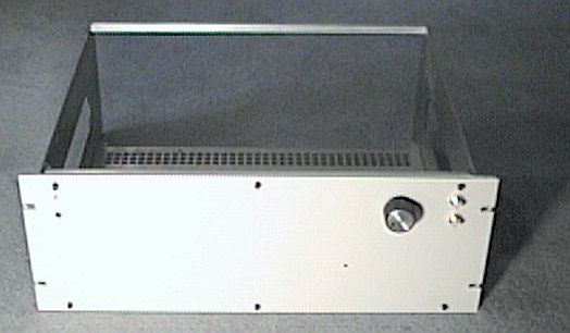
Original "blank" chassis is a "4RU" "rack". It looks like this. At the top right are input jacks and input attenuator. At to left are bi-colored LED power/status indicator and power switch.
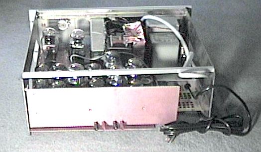
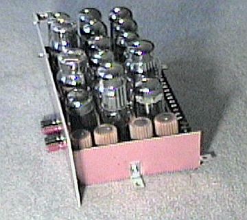
The 6080 "deck" looks like this. There are 18 tubes present. Some are 6080s; some are 6AS7s. Just about all manufacturers are represented: Svetlana, RCA, Sylvania, GE, Raytheon, Tung-Sol. The gold finned things are the 20 ohm 50 watt, 1% resistors. These will probably end up on their own sub chassis, as they add too much heat. Note the large "block" connector. All signals enter this module thru that big connector. #10 wire (and 0,24,30,36 volts for the heaters... 6x4+1+1 x 3 "rows" of heaters).
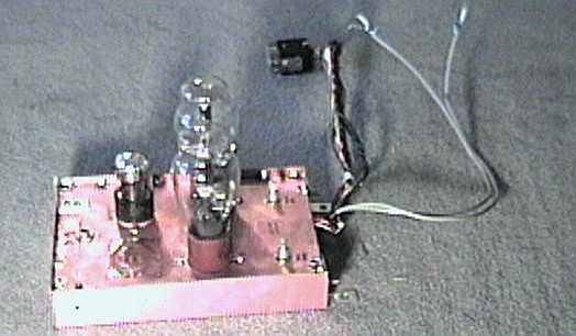
Here's the "input" and driver module. Yes, that's low capacitance coax to the output section, and the "jones" plug connects to the HVPS module. The input connects via a 1/4" "stereo" jack, visible on the left side. There's another "covered up" hole that I used during part of the initial driver stage evaluation. The 2 pots are hum balancing pots. Yes, that's a silver domed 6SN7.
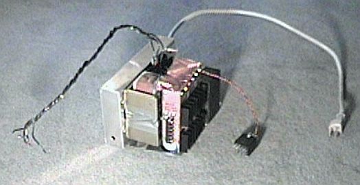
Here's the HVPS module. The "mains" enters this module. The black/white wires are to the power switch, the "loose" jones connector are the reference voltages for the LVPS. The chassis jones connector connects to the driver module. Note the power connector for the LVPS. Since this module develops "hazardous" voltages, the connectors are female.
Here is the LVPS module. You can see the 3 power transformers in this picture, as well as the heat sinks for the 4 LV regulators. There are 2 barrier strip connectors; one for the filaments (that's the one with the #10 wires connected to it for illustrative purposes), and a second set for +,+,-,-,Gnd,Gnd to the output deck. Just above that connector are the regulation voltage adjustments.
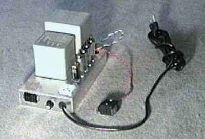
Here's the thing put together.......
There is a vented top/rear cover that then covers the unit. The 2 "dimples" on the "back" chassis secure that cover. There are no exposed "high" voltages either on the top inside, not from the "bottom" of the unit, although there is pretty good airflow through the unit.
What's next?
Revisit the driver only section. I want to compare 5 different output structures but keep the same operating point:
1. Resistor plate load capacitively coupled to the output transformer. (audition 1)
2. Plate transformer coupled. (uses a lower supply voltage)
3. Parafeed (ditto)
4. Constant current plate load capacitively coupled to the transformer: tube current source.
5. Constant current plate load capacitively coupled to the transformer: solid state current source.
Steve