There are a couple different ways in which multiple control tubes can be used in voltage regulator applications. In this part, we will discuss a couple of the more common uses.
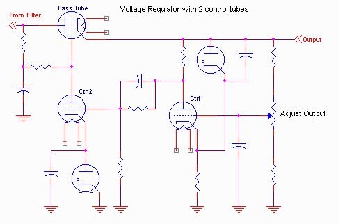
One reason to use multiple control tubes is to achieve more open loop gain in the regulator so that the voltage regulation is even better in the closed loop case. The problem with this approach is that as the open loop gain increases, it becomes more difficult to keep the "closed loop" regulator stable, particularly with different type loads. Characteristic of this type of regulator will be multiple capacitors that are used to tailor the regulator "frequency response" to maintain stability. Here is a circuit typical of this type regulator:

In this circuit, the output changes are mirrored at control tube #1's cathode, due to the coupling via the VR tube. These changes are amplified by control tube #2, used to control the pass tube. The ripple rejection of this kind of circuit is usually pretty good, and the DC regulation not too bad. One can typically get about 0.5 ohm output resistance (0.1 volt change for a load from 0 to 200 mA.) Because of the additional capacitors in the circuit, the AC and DC characteristics of this kind of regulator are usually quite different. Because of the multiple control tubes, and multiple VR tubes, it is usually difficult to get a wide range of output adjustment from this kind of voltage regulator.
One could add a 3rd or 4th control tube, but this is uncommon, since it becomes increasingly difficult to keep the resulting regulator circuit "stable".
Cancellation Circuits
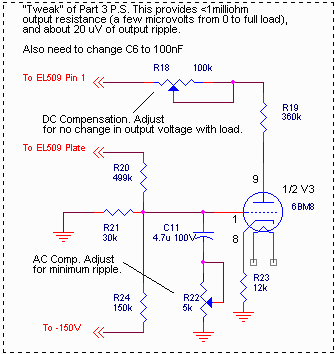
The other common use of a second control tube is to provide a cancellation mechanism for AC ripple, or DC regulation characteristics. I mentioned briefly in part 3 that an additional resistor could be added to the example regulator to provide essentially perfect compensation. By using a second control tube, it is possible to achieve this compensation without many of the disadvantages of attempting to do it with one control tube. Some of you might have noticed that the 6BM8 tube we used as the control tube in the regulator of part 3 is a dual tube; it also contains a high mu triode section that we did not use.
We can, however, modify the circuit of the regulator described in part 3 to use this second section:

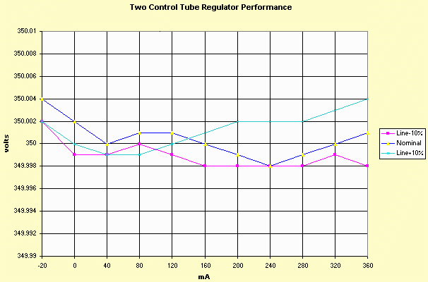
In this modification, some of the ripple as well as some of the line-change-with-load is fed into the grid of the otherwise unused part of the 6BM8. This is not a feedback mechanism, rather it is a "feed forward" style of compensation. It is usually possible to adjust the DC pot (R18) for either perfect line or perfect load regulation, but not both simultaneously. It is also possible to adjust the AC pot for perfect ripple cancellation or very low AC output impedance, but not both simultaneously. Here is the regulation characteristics I was able to achieve by adding this circuit.

Note that again, I had to change the scale of the vertical axis. Each box represents 2 millivolts!
The best ripple performance I was able to achieve with the values shown was 15 microvolts of output ripple, at any one output load, and about 25 microvolts ripple over the range of 0 to 350mA load. The DC characteristics I've shown above are just about at the limits of what I can measure with any degree of repeatability!
Sound? I couldn't make a definitive statement whether the part 3 regulator or the tweak shown above sounded better. I could convince myself that I liked either one better, but I probably would not be able to tell the difference in an "honest" A-B test.
This pretty much covers series pass regulators. In the final part of this series, I'll cover shunt regulators.
-Steve