Purpose
The purpose of this report is to provide a primer on vacuum tube based voltage regulator circuits. We will do this in several parts:
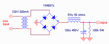
For all these circuits, we will use the same rectifier and filter section, so that you can see the difference in performance of the various topologies covered in this primer.
(c) Copyright 2000, Steve Bench. All rights reserved.
Part 1 - One Tube Regulators.
One tube regulators provide a form of electronic filtering, and some "load" regulation; that is, the output voltage remains fairly constant as the load on the regulator changes.
Since these simple regulators do not have a "reference", they cannot provide "line" regulation. That is, as the AC "mains" voltage changes, the output voltage will change as well. The lack of line regulation has one odd advantage: at low line voltages, the output drops along with the line, so the voltage drop across the tube doesn't drastically change. In part 2, when we introduce a reference, this effect will become more apparent, since the output wants to remain constant even at low line voltages. The consequence of that additional regulation is the possibility of the voltage across the tube becoming too low to regulate. These one tube regulator circuits do not have that problem. (see basics, below).
In all the examples shown, I will describe the "ripple" emerging from the supply, and graph the output voltage as a function of load. I used 60Hz "mains" in this example. Those with 50Hz mains will observe slightly more ripple for the values shown.
The Rectifier and Filter circuit used in the examples
Here is the basic power supply and filter circuit.

This circuit provides about 294 volts at a 50mA load and nominal line. It also produces about 800mV of ripple. At 20% low line, this voltage drops to 232 volts, at -10% low line, the voltage is 260 volts. At +10% high line, the output goes to 320 volts, and at 20% high line, the output climbs to 355 volts. The voltage vs load current looks like this:
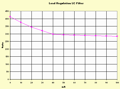
Notice that at load currents below 40mA, the voltage rises rapidly. This is due to the LC filter. At those currents, the critical current for choke input filtering is not satisfied. This is done purposely so we can see the effects of different regulators.
Regulator Basics
The purpose of a voltage regulator is to maintain a relatively constant voltage no matter how the load or power line changes. For the initial set of regulators discussed in this part, the regulator can provide some "load" regulation. This means that the voltage will remain relatively constant as the current drawn from the supply changes. A figure of merit for the "goodness" of a regulator is its output resistance. Ideally it should be zero. For the regulators in this part, it will approach 1/gm of the tube being used.
A good regulator should maintain the same output voltage when the line or "mains" voltage changes. This usually requires some form of "reference" tube in order to do this. For the regulators in this part, there is no "line regulation" capability. This means the output voltage will change when the line voltage changes. In part 2 of this series, we will discuss how to provide line regulation.
A good regulator should also improve the "output ripple" (hum) emerging from the rectifier and filter. A figure of merit for regulators is the "ripple reduction" provided. For the regulators discussed in this section, ripple reductions will be between 3 and 20 to1 ripple reduction. Part 3 will introduce improvements that allow better ripple reduction.
A typical characteristic of regulators is the ability to set an output voltage, independent of the rectifier and filter voltage. (Well, set to any voltage somewhat BELOW that produced by the rectifier and filter anyway). This is usually done by a potentiometer or voltage dividing set of resistors to the grid of the regulator tube. The output from the regulator is then typically the cathode of the tube. Since the grid doesn't draw current, this voltage divider does not need to be high power.
The tube intended to provide the regulation is called the "pass" tube. Good characteristics for pass tubes include high transconductance (providing low output resistance), high current capability (to allow maximum current capability from the regulator), and high power dissipation. The dissipation is the voltage dropped across the tube multiplied by the current delivered. For example, if the rectifier and filter produce 400 volts, and we desire to produce 250 volts at 100 mA, there is 150V*100mA=15 watts dissipated in the pass tube. Notice that power dissipated in the pass tube INCREASES as the output voltage is set LOWER, for any output current. We will discuss this further in part 2.
The Tube used in this study.
For this primer, I chose to use the 6KG6/EL509 as the regulating device. This is a beam power tube. In some of the tests, it will be triode connected, providing better performance than 2 sections of 6AS7/6080. It also allows us to use it in a "pentode" connection, to see if that is a help or hinderance in power supply operation. (Common wisdom suggests low mu, low plate resistance triodes).
The tube is capable of 35 watts plate dissipation, and 7 watts screen dissipation (for a triode mode connection capability of about 40 watts), 500mA maximum current, 18mS transconductance, and 900 volt plate rating.
Self Biased Triode Mode Regulator
The simplest regulator is a self biased series pass regulator.
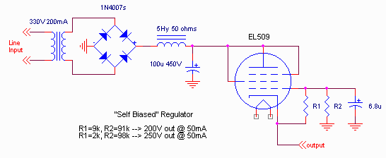
I've shown two conditions: one delivering 200volts, the othher delivering 250 volts. The regulation characteristics of this circuit are:
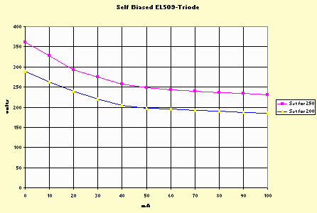
Notice that the voltage climbs pretty fast at low currents, and the load regulation is not quite as good as the choke input filter. What's the advantage? This circuit reduces the output ripple from 800 mV to about 150mV (250 volt case) or 200mV (200 volt case). When set for 250 volts, with -20% to +20% variation in line, the output voltage changes from 192 to 306 volts. When set for 200 volts, with -20% to +20% variation in line, the output changes from 154 to 245 volts. (at 50mA load).
Also, ripple can be further decreased by increasing the capacitor value on the grid of the tube.
Fixed Biased Triode Mode Regulator
The regulation characteristics can be improved by operating the grid from a fixed voltage divider from the choke filter output. This is:
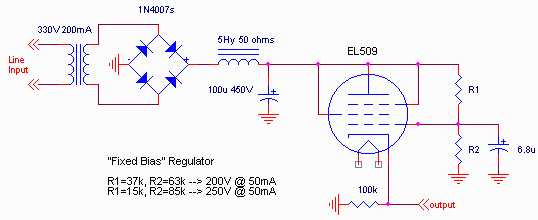
The disadvantage of this circuit is the ripple output is slightly higher than the fixed biased case: about 200 mV for either selected output voltage. Again, this can be improved by using a larger capacitor at the grid of the tube. The load regulation of this circuit is:
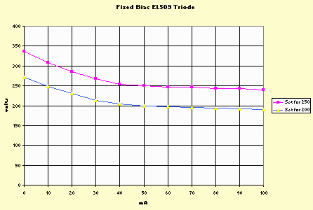
Notice that this is a good improvement, and as long as the input remains constant, the output is reasonably constant. The line regulation is slightly better than the self biased case. For the 250 volt case, with a +/-20% variation, the output changes from 198 to 305 volts and for the 200 volt case, from 158 to 245 volts. (at 50mA load).
"Improved" Fixed Biased Triode Mode Regulator
By noticing that the regulation of this supply is actually pretty good as long as the input to the regulator is constant, this suggests a "cheap" improvement. We could separately peak detect the output of the bridge rectifier (requiring an additional diode and an additional capacitor). Since the control circuit is relatively low current, and doesn't change with load, this means the detected peak will be relatively constant. This changes our circuit to:
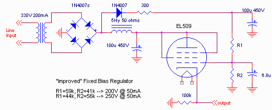
This also has a slightly lower ripple (about 150mV for either selected output voltage) and improved regulation characteristics of:
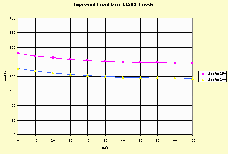
The line regulation is about the same, though: for 250v nominal, a +/- 20% change in line changes the output from 200 to 306 volts, and for 200 volts, changes the output from 158 to 243 volts (50 mA load).
Fixed Biased Pentode Mode Regulator
A pentode can be considered as a triode from grid to screen, and the plate as a current source. Thus, if we tightly control the screen grid, the same low output resistance can be achieved (good load regulation) with an immunity to plate variations. This, in principle could produce even better performance. Since the screen current is relatively low with respect to the plate current, we could also run the screen grid from our peak detected voltage source. The circuit is:
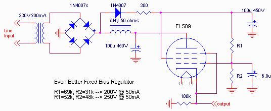
In addition, since the screen characteristics now determine the output regulation, the ripple is reduced to about 50mV. The load regulation characteristics are:
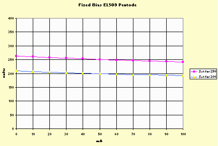
There are two points to note here: first, the overall regulation is even better, and the voltage variation with load is almost purely resistive. This would, in principle, provide a better "sound" quality in the amplifier run from such a regulator.
The variation with line is essentially similar to all the others: I measured 197V to 306V for the 250V case, and 155V to 245V for the 200 volt case (50mA load).
"Light(er) Weight" Versions
There is still one more variation we can consider. Since the pentode plate provides a high impedance isolation, ripple on the plate lead should not be coupled to the output. So, let's get rid of the choke. Here's the circuit:
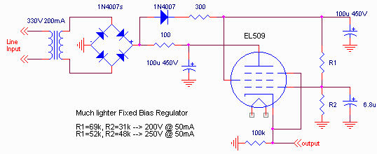
Guess what? The load regulation characteristics were essentially the same as the previous version, and the ripple increased to only 60mV. Line regulation was the same as the other circuits.
This provides the basics for simple one tube regulators. If you look at the curves again, you will notice that the effective output resistance of these regulators approaches 1/gm. This provides an indication of the performance you can expect with essentially any tube type in your circuit.
In the next part, we will add a voltage reference tube, to obtain some line as well as load regulation.
-Steve