Purpose
This article describes a power supply that can be used to provide relatively high voltage and moderate current for use in an audio amplifier (for instance 845 based). It provides a reasonably regulated 840 volts at up to about 100mA. This allows the builder to experiment at higher power levels without the worry about the sonic deficiencies introduced by the power supply. The regulation is shunt regulation, which is usually sonically neutral. Damper tubes are used as part of the bridge rectifier, so the supply has "slow turn on" characteristics.
Specifications (as built)
| specs | Output Voltage | Output Current | Ripple | Output Impedance |
| HV Output | 840VDC@50mA | 100mA max | 50mV | about 150 ohms |
| Input stage power | 120VDC | about 10mA | 50mV | about 200 ohms |
| 845 filament | 10VAC CT | 4A | --- | --- |
| Other filament | 6.3VAC CT | 2A |
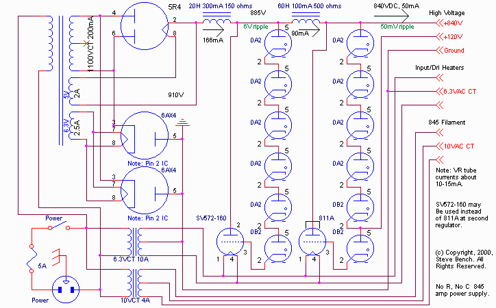
Schematic
Operation / Description
The supply is actually conceptually simple. It is a bridge rectifier followed by a two stage L-R filter. The "R" is formed by a shunt regulator.
The shunt regulators are SV572-160 parts (you can also use an 811A for the final stage - I did because that's what I had on hand at the time). These devices are very high mu (160) and are operated in A2 (grid current flowing). The highest grid current occurs at high line and minimum load and was about 35 mA in my case. This is within rating of the VR tubes and grid. The first stage operates nominally at 65mA plate current and about 11 mA grid current. This stage has to "absorb" high line conditions. The first regulator stage can tolerate about 170mA (135 in the plate at 900 volts for a power dissipation of about 120 watts, and another 35 mA in the grid (at about 40 volts)). This occurs with no "external" series resistance by working against the effective resistance of the power transformer, rectifier tubes and input choke). This is about 700 ohms, so a 10% increase in line voltage translates to causing about 170 mA in the first regulator stage. There is about 6 volts of ripple remaining at this point. The more current placed into the shunt regulator, the lower this ripple gets.
Incidentally, since the regulator current is determined by the effective supply impedance, it is NOT a good idea to use damper diodes as all 4 rectifiers. The relatively high internal impedance of the 5R4 actually helps.
The second shunt regulator stage operates at about 40mA current. Thus, the lower power dissipation of an 811A is OK, although a 572-160 will work better here (due to its higher effective transconductance as well as added plate dissipation capability). There is only about 50 mV ripple output.
The current in the first stage is determined by the VR tube values picked, the effective supply impedance, and the high voltage AC provided to the bridge rectifier. The output of the regulator may be set by the values picked for the VR tubes. In this case, I picked 5 0A2 (150V) and one 0B2 (105V) which, in this circuit produces about 885 volts output at the first regulator (855 volts plus grid to cathode voltage of about 30 volts = 885 volts).
Once the first stage is established, the regulator for the second stage can be established. In this example, there is 500 ohms of resistance in the choke between the first and second stage. To provide an output current of 50 mA (at idle in the PA the supply is used with), and 40mA in the shunt tube, 45 volts will be dropped in the choke, for an implied output of 840 volts. To make this happen, I used 4 0A2 + 2 0B2. This provides 810 volts drop in the VR tube, combined with about 30 volts grid to cathode, confirms the 840 volt output.
Since the filter is an L-R filter, there is a high ripple content until the VR tubes fire. This provides the additional voltage necessary to get them to fire.
Since there are no capacitors in the supply, the output shuts off as soon as the power switch is shut off (no getting zapped from the charge stored on the capacitors.) The supply also tends to be "quick", although there is about a 30 second turn on delay due to the damper diodes.
I also brought out a tap on the output stage VR string to provide incidental voltage for the input stage. It also has about 50 mV ripple on it.
Providing 6.3VAC for input and driver, and an isolated 10VCT for the output stage filament rounds out the supply.
NOTE: Since there is variation in regulation voltage of VR tubes, you may need to select from a group of devices to obtain the output voltage you want. Other than that, there is nothing particularly critical, but you do have to carefully choose your high voltage winding voltages, since there are no external resistances to otherwise limit currents in this supply.
What it looks like
Here's a picture of the breadboard implementation with the protective covering removed. It is indeed a "breadboard". The chassis is a 1"x12"x24" piece of wood. Notice that I used whatever inductors and transformers I had on hand to make up the total values shown in the schematic.
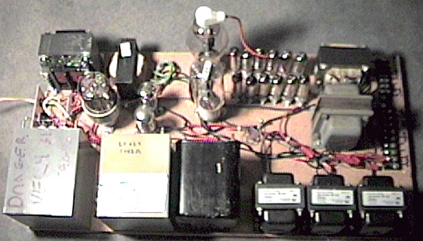
The small copper plate at the left houses the power switch and fuse, otherwise the rest of the parts are the mounted either directly to the board or to the board on standoffs. The sheet metal screw in the middle of the board below the VR tubes is the common ground return point.
The high voltage is wired with high voltage "test probe" wire.
The supply does produce a reasonable amount of heat; something in mind during experimentation or inclusion into your DIY plans.
-Steve