In this part of the series, we will cover an overview of the architecture of the preamp, the power distribution mechanism, the RIAA phono preamp section and the source selector, volume and loudness section.
An Architecture Overview
In order to accomplish our goals, some plan needs to be formulated. Last time we discussed some of the specifications, and what the overall preamp will look like. The method chosen to construct the preamp chosen was to segregate the phono preamp into it's own self contained box, and place all the remaining active componentry onto a separate board. This can be seen in the pictures shown in last section.
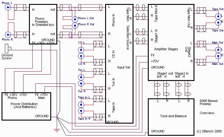
The remainder of the electronics is almost all interconnection wiring. This produces an architecture that looks like this:

There are a couple items I'd like to point out. First notice the shielded wire used to connect to the various parts of the circuitry. Also notice the single point ground used in the preamp. This schematic shows you how the different pieces connect.
Power Distribution
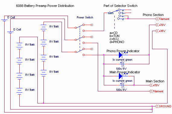
Actually, this is fairly normal, but accommodates a couple features not normally provided. The power distribution looks like this:

The unusual features are associated with the battery operation. First, it is not NECESSARY to switch the 72 volt B+, since the current consumption goes to zero when the filament power is removed. I did use that luxury on the 36V (going to the screen of the phono input stage), but chose to also switch the 72 volts. This is more for safety, since you can get a nasty bite from 72 volts, considering there's lots of current available from the batteries.
Notice that a third section of the input selector switch turns on the filaments to the phono section only when the selector switch is in positions c or d. As we will see, "c" section of the selector grounds the input to the line stage. This provides some time switching from "b" through "c" to "d" for the filaments to power up (direct heated filaments heat quickly). This eliminates some of the power on popping.
This also conserves power since the phono section does not draw filament nor B+ current until needed.
Also, two LEDs are in series with the B+ to the main section and to the phono section. The individual sections are well decoupled form the main battery, both to prevent any feedback problems when the batteries get weak and to prevent the LEDs from influencing the sonics of the preamp. Since a couple mA flows in each section, low current LEDs are needed, and they also provide a good indication of the health of the batteries, although they won't tell you the difference between a bad filament battery and bad B+ battery. However, since both "run out" at about the same time, when the LEDs get dim enough to be hard to see, it's time to change ALL the batteries. The 100uF across the LED also cuts down somewhat the bright flash of charging up the "filter" capacitors in the circuits.
The separate filament batteries for main and phono are more to avoid coupling of the directly heated filamentary cathodes than anything else.
Again, note the "single point ground".
Phono Section
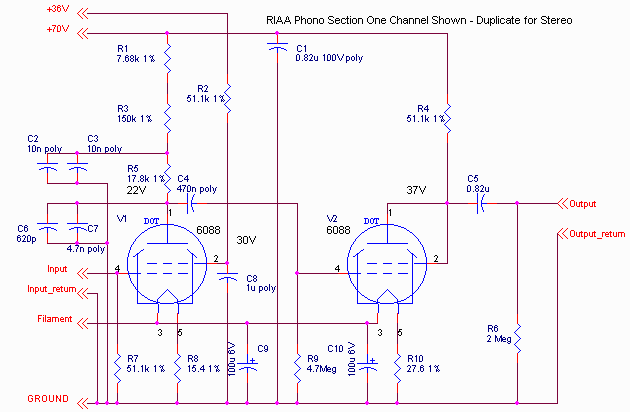
The phono section, as built, produces 34dB (x50) gain at 1kHz, and the RIAA compensation is flat within a couple tenths dB across the audio band. The noise measures 1-2 microvolts equivalent input noise, which, while not spectacular, is adequately quiet. It looks like this:

Only one section is shown; the other channel is identical. The form of the RIAA compensation used was chosen to provide as much B+ decoupling as possible as well as proper compensation. The plate resistance of the 6088 in the first stage is about 700k, and that influences the values.
Overall, I prefer the sound of the RIAA5 preamp shown on these pages, but this one is not that bad. Certainly considering the size and power consumption, it's quite good.
There's NO hum.
At all.
Microphonics with these tubes at very low (phono) levels is odd. Rather than the boink rattle (etc) one expects, the only thing I get is a low level tone of about 3.5kHz when you whack the box. I would not have expected such a high Q mechanical circuit. This can be damped. [I'm still working out a better damping arrangement, but you can see the foam around the tubes in the pictures shown in part 1.].
At the time I wrote this page, I have accumulated about 20 hours of listening on the phono section. I have not detected any degradation of the sonics as the batteries age, but I'm a long way from running the batteries to end of life.
Input Selector / Volume / Loudness
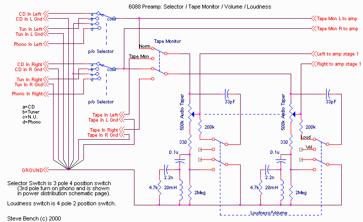
The selector, except as described in the power distribution part is standard. However, I did include a fairly exotic loudness compensation circuit. This was previously described in my pole/zero analysis series on these pages. Overall, it looks like this:

Also of interest is the isolation for the tape monitor. This prevents tape recording (or whatever) from affecting the sound otherwise going through the preamp. Also, sometimes this machinery presents a low impedance load when connected but turned off that would affect performance. This will be described in the next part of the series.
If you flip between the overview schematic and this selector schematic, you will get an understanding of how shielded wiring can be incorporated without causing any ground loops.
There is one additional use for position "c" of the selector. I have provided a separate direct phono output. In this position, the line stage is not connected to the phono, so the direct output has no "internal" loading on it, making it the right position to use for using that feature. Also, since this "grounds" the line stage inputs, you can also evaluate the line stage noise very conveniently.
What's left?
Line section amplifiers, tape monitor amplifiers, tone controls.
-Steve