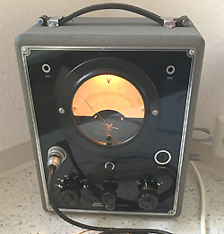
Repair of a Philips GM6004 Diode Voltmeter.
About this GM6004
 The first version has the genuine Philips side sockets, and a huge, multi-tap potentiometer which is used to calibrate all switch ranges.
The second model GM6004-2, is what this report is about. It has Rimlock tubes, and the calibration is done with hand selected resistors, on a panel you can conveniently access from behind to service it. However the calibration was done with great perfection by Philips, this needed no adjustment at all, even though the resistors are 75 years old.
This GM6004-2 belonged to Radio & TV repair man in Vlaardingen, my birth town in Holland. He bought it new in the 1950's and used it until he retired in 1979. So he used it 'only' 25 years. My father got hold of all his old instruments, and one day brought all of this a gift for me, and this GM6004 was with it. So it has some good memories to my father, which is the reason why decided to restore it now in 2020. So it was used 25 years by it's first owner, and then stored 41 years by myself.
At first I thought this instrument was nothing special, a bit clunky, with that strange looking probe. It responded to voltage, but that was all there was to say. Just knocking on it made the reading change already when I got it in 1979. The zero setting was unstable, the needle was never on one position at a time. That was as the reason I never did anything with it than switching it on occasionally to preserve parts and tubes. But it got worse over the years, and now it indicated only mess. Yet when it was finally completely restored, it turned out to be a within 1%, and stability is so perfect, you would not never believe this is a tube amplifier.
Also the wiring inside is flexible and still 100% good. Same for the probe cable. It's soft and flexible like new. So why are new made cables so stiff, and crack after 5 or 10 years? Ask the Chinese! But this 75 years old Philips Holland machine doesn't have such problem. (But a few other problems it had)
The case paint looks really dirty. But this is wrinkle paint, nowadays re-discovered again by freaks. Such paint can be beautifully restored like new, without taking it off. Just spray an ultra thin layer of opaque paint just over it, in the same color, and the wrinkle paint looks like new. You can have the right color prepared in a car paint shop, and the front plate can be conveniently be removed for this. I might as well do this perhaps even.
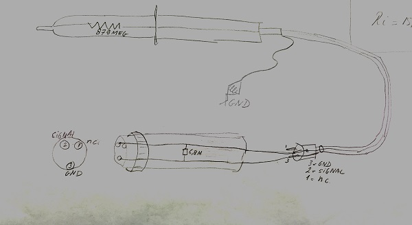
When it's fully restored, what do we get? Well it will outdo a passive analog volt meter of course. That is what is was made for. Still this powerful electronic volt meter can keep up with modern electronic devices very well. Yet a disadvantage is, it has no normal 4mm (banana plug) inputs. Though this would have been really simple to achieve, but you loose the "active probe" concept of this meter. At a few specific point it scores really good. That is the high frequency range, up to 100MHz, when using the active probe, the impedance is 879 Meg, the lowest scale is 300V and the highest 30kV. So for radio amateurs, it may be useful.
How this meter works.
Rectification is done directly inside the probe, with a tube diode. So any problems with cable capacitance or length, you don't have. This brings down the input capacitance to a fabulous 5pF.
A compensated tube Op-Amp.
The EZ50 tube diode in the active probe, has a thermionic voltage of itself, which must be compensated in some way, because t his voltage is relatively high. To get a good feeling for what this is, just take any random electron tube you have, let the heater glow, and measure the 1...2V or so voltage between cathode and grid. So it obvious, this obstructs the measurement when such a diode is used as a rectifier. Besides the diode has a forward voltage.
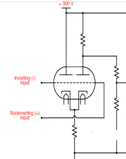 To compensate all of this, the measurement circuit is duplicated. So inside the GM6004 is exactly the same rectifier diode, and another EF40 pentode, amplifying it's output signal. These two EF40 are now in an Op-Amp configuration. The picture in the left is with triodes, it is easier to understand and it works the same.
In function this becomes an Op Amp. The non-inverting input is grounded, so one of the EF40 and it's diode is only used to produce the same thermionic error as the other half. There is also an adjustment for the balance between the two EF40, which equals the offset potentiometer of any silicon Op-Amp. Given the amazing DC stability, linearity, and frequency range of this circuit, I can say it works really very good.
Calibration
The calibration is easy to do yourself and the circuit is straight forward. If you like the fun of getting such an old equipment in top condition again, they are easy to find in raw condition, and cost not much. It is quite some work, if you don't want to skip things, like making the switches run smooth and all of those details. But none of it is difficult. Anyway, the result is much, very much better than I thought.
The Chassis and the probes
The chassis has just one connection as a DC input, with highest sensitivity 1 Volt full scale, at 5.1Meg. So clearly, this is a high voltage meter, and not a millivolt signal meter. The connector also offers 6.3Volts, to supply the tube diode of the active probe.
The AC / DC Probe
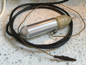 Then, with the active AC / DC probe, which gives also a factor 1:3 attenuation, an impedance of 15megs at 3Vols is achieved.
The High Voltage Probe
With the 100:1 DC High voltage (Passive) probe, all voltages are attenuated 100x and the impedance becomes appr 880 Megs at all ranges. The cables and connectors are the same as for the 300V probe, meaning there is a 6.3V AC connection to this probe, and because it is transparent, I am tempted to put a small light bulb or white LED in there, so to illuminate the device under test :)
Repair report
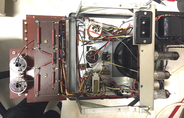
You can can remove this plate easily to work on the inside parts. You can even switch the unit on like this.
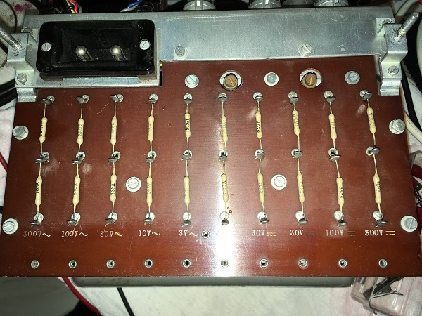
This is the calibration panel. Each sensitivity range, AC and DC has it's own meter calibration. This is fantastic. There is nothing I needed to do here, but in case it is needed, a fixed resistor is at the other side, and these two smaller (cream colored) resistors are in series. These are hand picked, so values are individual. You should only use this for very fine adjustments BETWEEN the ranges. Overall calibration is simply done from the front, via two pot meters. One for 3V and 10V together, and one for 100V and 300V together. So instrument precision was sure an intention here.
Bad solder joints. Obviously never anything was de soldered before, because all solder points were marked with a color pen. Yet I found three bad joints, close to the probe input.
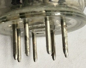
Tube pins. 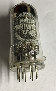 The EF40 and EZ80 tube pins have a thick silver plating on them, which turned totally black. I do not know if this thick plating was a Philips standard or specially done for this instrument only.
It was not just this blackening of old silver, but a very nasty layer of something. The EZ80 didn't seem to have a problem with it, but the EF40 when I knocked on them, responded badly, and the needle would take another position every time. I put the tube pins in 25% vinegar, really strong stuff, but even after 4 hours, it was not really gone. So I just rubbed it clean with abrasive powder and an old tooth brush. I sealed the tubes with a plastic bag and tape, so not to damage the nice printing on them. The pins are optically not shiny, but electrically clean again. You can still se the silver flaking off a little bit from one pin.
The scale lamp. 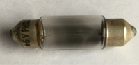 It has the original Philips 6844 scale lamp inside, and it is totally blackened, giving some indication of the use time. Since this is just a 6.3V car lamp, this is likely the original lamp. I estimate such a lamp to look like this after some 1000 hours. Which was an average if 1 hours per week. That seems to make sense, because he may not have needed a diode voltmeter every day.
Carbon resistors. The GM6004 had only two of those, and they were bad. Value had gone up some 20%.
Capacitors. It has only four of them, because the circuit is basically DC coupled. There is one High Frequency capacitor in the probe, the value is not in the manual, but I found it to be 40nF and no leakage at 500V (I don't want to test it higher) Two more capacitors of 12.5uF are in the rectifier circuit, and they are still fine. No leakage and low ESR. The DC put voltage is 230V as it should be, current draw is 11mA, also by the service manual. What sure saved them, was the regular switching on, I did over the years.
A fourth capacitor of 47nF is at the input, it just seems to be there to suppress AC, because the probes deliver DC always. This seems a very special one, with Philips coded printing on it, and it is some sort of a low leakage capacitor (probably). It had a weird defect. I would advise GM6004 users to replace it always. This capacitor had a voltage dependant leakage, which is not there below 100V. Above 100V, the leakage comes in slowly, and at 300V it leaks 2uA. This caused a strange linearity error. It took me a very long time to find out the reason for that! So better replace that capacitor, even when it looks good to you. I tested the cap only at 100V because that is how far my previous capacitor tester would go. The Heathkit I-28 picked it out right away. (Very much advised capacitor tester - unfortunately much sought of, and costs you 200...300$ on Ebay)
So I wanted the best capacitor possible in there. Such a replacement you will not find. So I put two Siemens Styroflex capacitors of 100nF 160V in series, to get 50nF 320V. Styroflex have the lowest leakage of all available capacitors. These are becoming harder to get today.
For my curiosity, I opened up the defective capacitor, and I found also what perhaps caused the problem. Frankly, I found it isolated not so ideal, it had only a single layer of isolation. A better way is a double wound foil package, which would have the same effect as two capacitors in series. The isolation inside was paper. Today's plastics are better. The reason this capacitor became bad, I found also. It had to do with the way the foil was connected. There was a very thin layer of solderable foil rolled into it, which disappeared into the CENTER of the rolled up foil. So this was intended for the electrical connection. This solderable foil however was not covering the full width but only half of it. Which to may opinion is a mistake, and the cause for the failure. It could be clearly seen, the paper was impaired by the sharp edge of this foil. I have made pictures of this. Since this capacitor is directly in parallel to the high impedance input, any leakage of it, no matter how small, is inacceptable
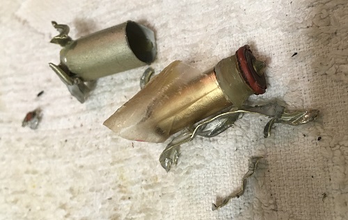
What a mess :)
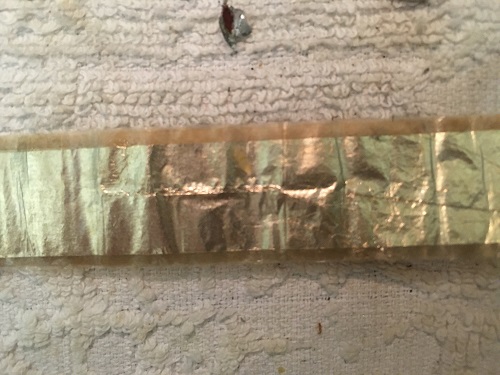
The horizontal stripe in the middle shows how the contact foil pressed on it, with an imprint. It became a voltage dependant resistor, but no real short. That is why I wanted to see it what it looks like.

This is the contact foil, causing the imprint. It looks zinc plated copper to me, at least it is solderable as you can see, and the capacitor leads were soldered on it too. This foil has sharp edges and nothing was done to protect the isolation foil.
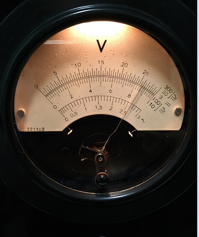
The panel meter itself . It seems a 100uA full scale meter, and it showed only 95% full scale at 100uA. The magnetic shunt had more then enough reserve, and I could nicely calibrate it at 100uA. Inside are damping resistors in parallel, this protects the movement nicely, and I guess it is a 50uA movement, same as in multi meters. I noticed the meter seemed a little but unbalanced, so there was a 5% difference between the upright (intended) position, and laying flat position. However the meter was showed EXACTLY the readings on the scale. So no need touch anything.
The set zero potmeter. It went extremely heavy, but with cleaning alcohol and oiling the axis, I could loosen it again, without having to remove it. Since the "feel" of this one is excellent, and stability too, I decided to leave it it, but otherwise at the slightest sign of instability, I would say replace it immediately.
The range knob, and +/- knob. They went much too heavy. Terrible. After removal of the knobs (what a construction!) I could reach the axis and oil everything. With some fine oil, and a lot of use, they became loose.
The calibration pot meter for 10V.
This one is very important, and a lot of the stability of the whole tester seems to depend on it. Instrument quality 1 Meg pot meters are not made any more. I did not want to use the Chinese pot meters that are throwing at you on Ebay, but I found a vintage pot meter from Japan, and it worked very good. My advise is not even think of leaving any of the old pot meters in. I have the same experience with L3-3 tube testers, for each old pot meter you replace, the stability of the whole tester improves.
The case
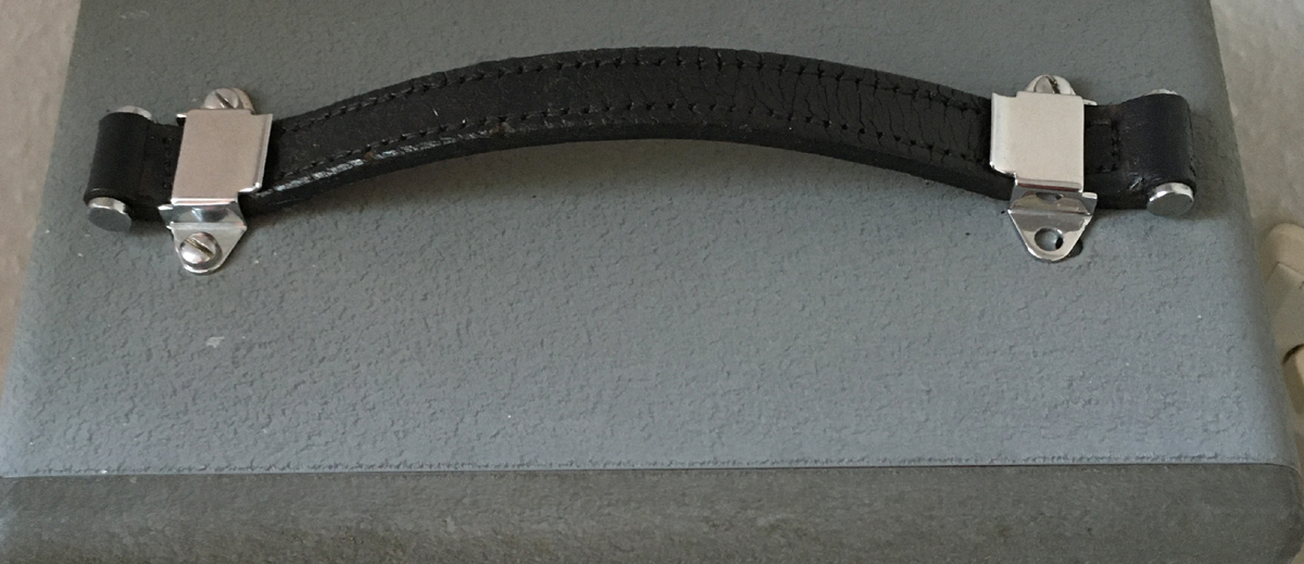
The leather band was powdery dry, but just fair enough to use it. I painted it with just normal black acryl spray, and it looked like new. I don't know if there is special about painting leather, but this worked just fine. After drying the paint, I warmed up the leather with hot air, and soaked it with vaseline, it became smooth again. Well it's not like new, but very good looking again.
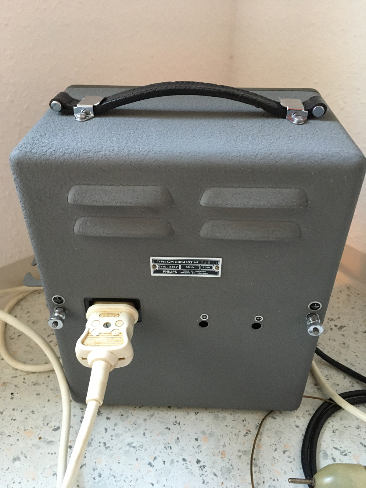 The case I cleaned with a stiff brush, water, and cleaning fluid from the kitchen (this white abrasive milk). I did not trust to clean the paint of the front panel with that, because sure this milk will creap underneath, and I don't want it there. So you can see at least now, how clean old wrinkle paint gets from abrasive cleaning fluid.
The crome parts of the handle, and the ground scews at the back, were soaked 30 minutes in concentrated (25%) vinegar, the dirt could be brushed off with abrasive milk, and they shine like new.
An interesting observation
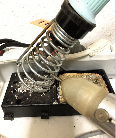
With the low voltage probe, the impedance is 15 Meg at all DC ranges, but this impedance gets a lot lower at radio frequency. Yet at just the mains frequency, it seems to outdo all (silicon) electronic meters which I have. Here is an observation, which demonstrates this. With the probe om AC, I just touched some random objects on the bench, including my Weller solder iron. This has a ground connection, which I prefer to leave disconnected, so I can solder or touch by mistake some electronics with a voltage on it. This means it is floating, but not free of AC voltage. This AC voltage is relatively high, because via the transformer, cables and the switch, the solder iron is capacitively connected to the mains. However this voltage is very high impedance of course, so it can do no damage. The AC probe measured 10V AC on it. This is more than I expected actually with 15 Megs load on it. It is still 0.7uA. Probably this voltage is a lot higher without the load of the GM6004 probe
Then when I put the solder iron inside that metal spring like in the next picture, I measure on that spring still 2.6V AC with the GM6004. When I take the solder iron out, the voltage is gone. Where is this voltage coming from? Well the spring is not connected to anything, but the black plastic piece is obviously conductive plastic, for ESD protection purposes. So I have now in series: 230V from the mains, the capacitive path to the solder iron tip, the conductive plastic, and the metal spring.
 .
.
When I connect the probe to it, the voltage drops from 10V to 2.6V. When I take out the solder iron, the AC voltage is gone.
Then, I connected my Agilent 34401A to it, which is top class meter, everybody will agree. Then what happens? It indicates only 1.7V. So it has lower impedance, which is indeed so, because it is 10 Megs by the books. If I connect both meters in parallel, it stays at 1.7V. So the GM6004 has no effect on the voltage. Just when I remove the Agilent 34401A, the voltage rises again to 2.6V. The interpretation of this observation is difficult, but is showed to me how high the impedance of a tube grid really is. So for any future measurement, when I want the possibly lowest load on the circuit, right now this 70 years old GM6004 is the best meter I have for this.
The above was measured with the low voltage probe. (Well it can do 300V)
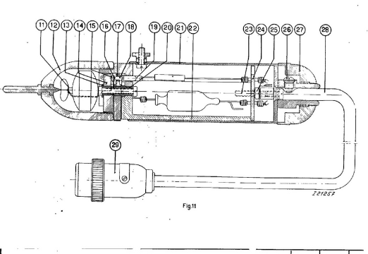
Using GM6004 with the High Voltage Probe GM4579
I found no information about this, but I did find some documentation about using GM4579 with the GM7635 electronic voltmeter. However GM7635 has only one tube, and it misses the compensation principle of the GM6004. So GM7635 is by itself unlinear, and the meter scale compensates this. Whereas the GM6004 is very linear, it works like a compensated Op-Amp, and theoretically any other good panel meter could be used.
The probe GM4579 basically can be used with any equipment whatsoever. It just needs the appropriate load. This load is found inside the connection adapter which is needed to connect GM4579 to GM6004. It's value is 6.8 Meg. I found this value in do documentation, but it was just the color codes of the carbon resistors inside. These were totally off and I replaced them with new metal film resistors. When I was done, I found a value of 7.1 Meg. So the resistors were not so awfully accurate. Also such high values are not easy to measure very accurate. So I just used these and it turned out to work good.
Inside GM4579 is only a resistor of 879 Meg, in series with the probe tip, and nothing else. So when GM4579 is connected to an input impedance of 8,87 Meg it becomes a 1:100 attenuator.
Connecting the 1:100 probe to GM6004 works as follows: The impedance of the direct input of the GM6004 is 5.1 Meg, and if gives a full scale reading on the 3V scale at 1 Volt. So it amplifies 3x. (*1)
The calculations for this is as follows: 5.1Meg // 6.8 = 2.97 Meg. The attenuation is now (879-2,97)/2,97= 294x. Given the gain is 3x, the attenuation is 98x. (Reason why it is not exactly 100, is because I measured the resistances not with enough accuracy. When testing the probe, it is exactly 1:100 though.
What is interesting to do is this: I can detect a static electric field, radiated by an isolated wire with 500V DC on it. When I approach the wire quickly with the probe, the meter needle moves to +7V fro 1/4 of a second. When I remove it, the needle moves to -7V. The explanation for this is, the probe tip has some capacitance, and the changing electric field creates a small current into that capacitor. Which means positive electric current flows into it, and this created the +7V across the 879 Meg resistor. 7V equals a current of 8nA.
*1 With the standard AC/DC probe, which has a series resistor of 10.2 Meg build in, it becomes a 15.3 Meg impedance and 1:1 reading.
Conclusion.
- This voltmeter together with the high impedance probe can do some measurements which can not be done easily with standard equipment. Though I am not a radio amateur, and also I am not working with very high voltage or nano ampere current, I have little use for it. Still this instrument is a beautiful example of what tube technology is capable of, if made by a company like Philips at the peak of it's "tube" capabilities.
- The stability of this DC coupled amplifier is excellent. I did not expect this was possible. Within seconds afte the tubes begin work, the meter is already stabilem, though you need to warm it up of course still. There is nothing whatsoever which reminds me there are tubes inside, not even it's power consumption of 20 Watts, of which 5 Watts are for the light bulb.
- Note: In case you want to restore one yourself, it is really nice to do, and not really difficult, but you do need to replace all calibration pot meters, and some of the internal parts, and restore the probes with patience. Yet the function is easy to understand, and the chassis not difficult to work on, but I wrote this for the GM6004-2. I can not speak for the first model GM6004, which is constructed very different in detail.