© COPYRIGHT NOTICE All Rights Reserved
![]()
Portrait of a tube
The terrible confusion with VT25, VT25A, 10, 10Y
(Confusion not resolved here)
(Last updated:
17-Feb-2018 17:52
)
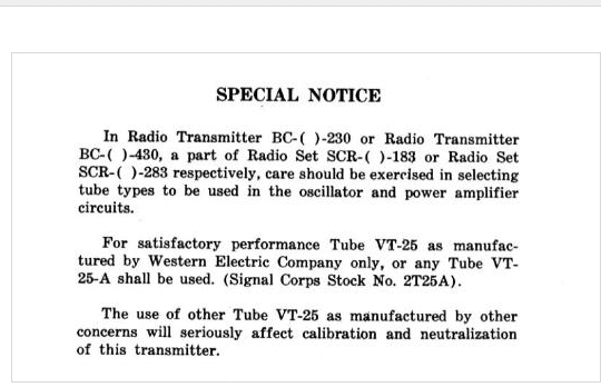
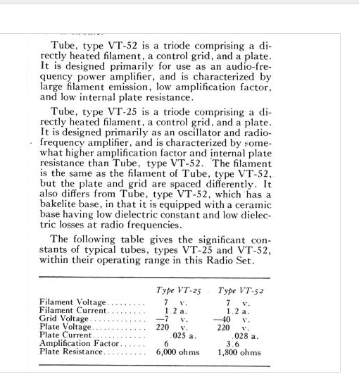
This is about the VT25, VT25A tube in general, and how to test them. We need to keep apart, there are two kind of those tubes, the one has a Barium Oxide coated heater, the other has a Thoriated Tungsten heater. For optical reasons, there is no doubt, the Thoriated Tungsten heater is looking nicer. The Barium Oxide coated heater is a later development. There is great misunderstanding in the HiFi community, thinking these tubes are "the same" apart from the heater technology. In the manual of a Western Electric transmitter, we find something different. We see here clear warnings, these two types cannot always replace one and other. With WE being also a manufacturer of the VT25, this the one and only piece of TUBE MANUFACTURER data about VT25 I have ever found. Even more confusing is, the part number VT25 was used for Barium Oxide tubes by WE, and for Thoriated Tungsten by the others. Confusion comes also from the Catalog of Navy Material calling the VT25A a "10 Special". Which is not the right wording. VT25A was not a "10" for a special purpose. It was a new development. Whearas RCA called their 10Y a "10 Special", which is correct. And there you are, more confusion. There were some request for test cards for VT25 and VT25A, but first hand data is unavailable. "VT" Part numbers are military. From what it seems, the official specifications have been kept secret ever since. If you don't believe it, please send me the original documents. You will see, there is only information around from people and companies who wrote documents themself, but no official datasheet from companies who actually produced the tubes. The only official document I have ever seen, is from Western Electric, and this is mostly incomplete.
In such a situation, fake information spreads rapidly. It begins to look real, when everybody copies it from others. So I will change it here when I am wrong, but I think we can say, official VT25 or VT25A datasheets were not published. Unofficial data can be found, vut waht fails, is a tube manufacturer's document. The Western Electric VT25 is a Barium Oxide coated tube. This particular tube is a special situation, and it helps to understand better what happened. There are fragments of informatiom found in the Western Electric Service manual for their airplane transmitters. However, this is helpful, as they are a manufacturer of the tubes, and manufacturer of the amplifiers at the same time. By reading those rare documents we can draw some valid conclusions. We combine this with the knowledge, that all VT25 made by Western Electric are Barium oxide coated tubes, so no Thoriated Tungsten heater type. There are very rare copies around of the Service documentation for Western Electric transmitters, like BC230, BC240,SCR183 and SCR-68-A. The warnings in the below document clearly aims for the use of Barium oxide coated tubes only. If this is disrespected, there will be serious problems with calibration, and neutralization of the transmitter. They write: Use only VT25 if made by WE, or VT25A from other companies. This makes sense, because VT25A from other companies is always Barium oxide coated, and so is VT25 made by WE. So we have already here the situation that the Thoriated Tungsten version, and Barium oxide coated version, according to Western Electric, are electrically so much different, you cannot use both types in the same amplifier. As they write, you get serious problems. From an engineering point of view (calibration and neutralization), it can be concluded, tube dynamic parameters and capacitance is not the same. But there is more. Western Electric writes "VT25" has a 7V heater. But we need to know, their VT25 is Barium oxide coated. So we have to be more precise: The Barium oxide coated tube has a 7V heater. Wheras RCA 10 and 10Y has a 7.5V heater by the datasheet. So by Western Electric, when comparing the Barium oxide coated version with the Thoriated Tungsten version: electrical parameters are not the same, and the heater voltage is not the same. (7V vs 7.5V) When looking inside a VT25A tube, if glowing at 7.5 Volts, anybody can immediately recognize the heater burns much too bright at 7.5V! This obervation I made immediately after swithing a VT25A on, at 7.5Volts, and from there I started looking for more information. To my opinion it burns only at the correct orange color, if the heater voltage is 6.3 Volts. After some searches in the internet, you find everywhere VT25, VT25A is a "10". Just a datasheet is painfully missing. So how do they all "know"? Particularly because it is so clearly visible the heater glows MUCH too bright at 7.5V. I am working on a test method, to find out the real heater voltage of any random tube. So that's a project to follow up in this item, later. There is an interesting historic document, explaining the use of those tubes in airplane transmitters, where the voltage of a battery under full charge is 7 Volts and only 6.3 Volts for a charged battery with the engine off. You can still today make the same observation with a "12"Volt car battery. They are identical chemistry, only 6 cells instead of 3 cells of the 6V battery. A fully charged car battery has 13.8 Volt with the engine running, and 12.6 Volt with the engine off. Divide those numbers by two, and you get 6.3 and 6.9 Volt. My personal observation is, the Barium Oxide versions is just a 6.3 Volt tube. So all they did, was specify this tube at 7 Volts right away, because those transmitters were only used on the air, and then the battery voltage becomes 7 Volts anyway. Adding 10% to 6.3V gives 6.9 Volt, and 10% is indeed the theoretical maximum over heating of a Barium Oxide tube, with the a compromise on use hours, but no heater breakage. Go above, so 11% or more will break the heater unexpectedly. 7.5 Volts is 19% (!!) above 6.3 Volts. So it takes little expertise, to understand you should NOT use the Barium Oxide versions at 7.5 Volts. Type "10" and Type 1602. There is an RCA version with low microphonics, called 1602, and RCA writes in the datasheet, it is an upgraded version of the "10". The 1602 has more information in the datasheet. So that is a good source for missing information about the "10". Such as a nice chart for instance of Gm vs. Ia, which is unspecified with the 10. We have to take the word "unspecified" as it is. So for the 1602 the tube has to comply with those curves. If they do not, but seem fine for the rest of it, they can still sell it as a 10, and it's perfecly legal. So you might find identical urves with a ramdom tyope 10, or just different. The same is true about microphonics. A tube which fails the 1602 microphonics test, may still be a good Type 10.
Testing the 10, 10Y, VT25, VT25A In the early days of radio, when this tube was designed, the electrolytic capacitor for the power supply was expensive and amongst the first parts to fail when equipment got older. A working voltage of 250V DC was possible to achieve conveniently and reliable. However, above 250Volts, the capacitors became expensive. This is just the reason we see to many old equipment work on a power supply of 250Volt. In many old datasheets we see this working point of 250V, along with the technically better working points. Yet for tube testing, there is nothing wrong at 250 Volts, and also tube testers get a lot more expensive and more dangerous too, when the have to work at 400 Volts or more. That is the reason, many tubes which are working best at higher voltage around 450V, are tested only at 200... 300V. For the L3-3 tester, it cannot test conveniently above 300V, and there is a test point mentioned in the RCA "10" datasheet of 250V. So we have two test cards for this tube: 1) 250V Card. For just tube quality testing, this card is adequate. There is not much to say about this card, it tests at the RCA data point of 250V. Suppose the fails ar 250V, nobody can be seriously interested if the tube appears "good" at 425V. It's a bad tube still. So for quality testing, 250V is fine. 2) 425V Card. The L3-3 theoretically was not intended to test at 425 Volts DC, but as long as plate current is low, this seems to work well. The tester by itself can be tests rectifiers at 550Volt AC, so switches and cabling can do it. With the help of an external voltmeter, you can set the anode voltage at 425V as well. I do not know where the limits of the L3-3 are with these kind of things, but it as long as we do such tests at relatively low anode current, it works good. To measure the anode voltage, you need to connect an external voltmeter to the tube deck, to Banana Plug "A1" and the tube deck "Ground" plug which is close to the mains inlet. When you do not want to go this way, use the 250V card. VT25 Usual VT-25 have thoriated tungsten filaments. Only Raytheon (4 pillar & box plated) & WE VT-25 have oxide-coated filaments. Moreover Western Electric writes here, VT25 if used in their amplifiers MUST have a ceramic base. (This material has lower capacitance).
Here is an article about the SCR-68 (which is not SCR-68-A!), SCR 68 seems to use 20 Volt heater tubes. It does However, nicely explain the problems and requirements in those days. VT25A has heater voltage 6.3 .... 7 Volt. VT25A was always a Barium coated tube. In lack of a datasheet, people "say" they are electrically the same as VT25 and the 10 Thoriated Tungsten. This is technically not possible because emission behavior of a Barium Oxide tube and a Thoriated Tungsten tubes is quite different as a matter of principle. Moreover, VT25 (oxide coated version) is documented by WE as 7V tube, and the 10 is documented as 7.5V tube. There is little acceptance for how precise heater voltages of DHT have to be, but you cannot force your opinion on the tubes. The maximum deviation of heater voltage for all DHT has always been +/- 5%. Unlike what many people think, this doesn't mean within those 5% everything is the same. Rather when you pass the +5% you will have lifetime below minimum specifications. At +4% you will have slightly higher lifetime as minimum, and so on. The highest possible lifetime is reached at 100% of datasheet value. Going below the datasheet value is possible too. Again we have this -5% below which you will get problems. These will be loss of emission, due to poisoning, or due to lack of regeneration of the Barium layer. Moreover, there is the variation of the supply voltage for AC heated tubes. So make a good habit of it, to target exactly for 100%. What happens when you exceed +5%? The answer is simple: The lifetime of the tube will reduce below minimum specification. Moreover, above +5% you have an realistic chance to see a heater breakage. This risk grows almost 100% within 500...1000 hours, if you exceed the heater voltage by 10%. There will always be fools, who want to learn this the hard way of course. Let me give an example how mistakes are repeated. A person at radiomuseum.org registered the VT25 in their knowledge base with "7.5V heater". Under data source is written: "Taschenbuch zum Röhren-Codex 1948/49". I searched for what that is. And then it was just information scraped together in a 1948 pocket book, without reference. So where this man had the information from, he finds it not necessary to say. And this is always the same, where ever I look. Everybody uses a reference to another reference, and no original data. So I did the following: I have here in my collection two NOS "Hytron VT25A, made for Western Electric". They were in original Western Electric boxes. The boxes were still sealed with a metal staple before I bought them. So I glow these tubes at 7.5V, and the first thing I see: This is a Barium coated tube, but it can never be a 7.5V heater tube! Let's just say Western Electric would never accept any second class stuff, with the wrong heater voltage by mistake. So the tube is correct as it is. Only, what I see, it glows TOO Bright at 7.5V, which may be right or wrong, I just don't know. From here my search began. The heater current of this NOS VT25A is indeed exactly 1.25 Ampere at 7.5V. Measured with AC Voltage. Very confusing, because it's just the same as the RCA 10. However, these Barium coated tubes produce much "better" data as the RCA datasheets. However, there is not "better" data. The best data is original data. So those VT25A do NOT test as a type 10. So at the same grid voltage, they draw more current, and even at the same current, they have higher Gm. Since VT25A is a barium tube, this doesn't surprize me. In lack of virtually any other source of information, I will use the test data of those two NOS tubes for VT25A. Also because they test so nicely identical, like twins, chances this data was intended seems higher to me as chances this data was by wrong by coincidence. As said, it is the only data I have, of which I know for sure it is right. This data was used for the VT25A test card (Version 42) and perhaps I must change it later. Better would be to have original VT25A specs. Here is some of the information I collected, with the source.
I found this here: http://audiokarma.org/forums/index.php?threads/vt-25-a-is-we-vt-25.35953/ VT-25-A means VT-25 with oxide-coated filament Hello Jack The first VT-25 with oxide-coated filament was employed by SCR-183. Around 1939 Raytheon stopped manufacturing of VT-25 & VT-52 My conclusion is
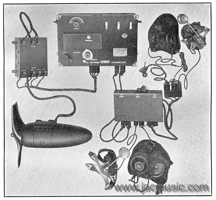
Sometimes we think of those old airplanes are flying junk, but check here, how nice it looks, when it is new made. On the bottom is the Western Electric SCR 183 amplifier installed.
|


© COPYRIGHT NOTICE All Rights Reserved
![]()