Portrait of a Tube
RS242
By coincidence I was able to buy a pair of NOS RS242. When looking inside I was immediately intrigued by the build quality, and also by the plate color.
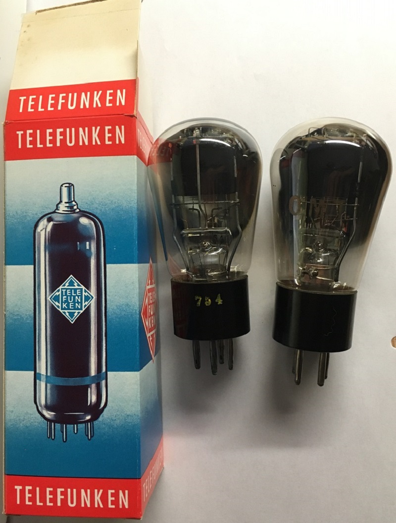 Now you see, there is a black plate version and a grey plate version. The darker the plate, the better it gets rid of the heat. These plates however are so deep black, I have never seen this before. It has such a strange effect, it is like a black hole. There is no light coming back from it. I suppose probably few people have been inside a acoustical "dead" room, with the sound absorbing walls. It is highly uncomfortable in there, though you can speak and hear things, there is no sound reflection. A similar effect I had with those Telefunken RS242, it is like staring into something dark, there is reflection whatsoever. I have never seen this before.
Production
 This tube was only made by Telefunken under the RS242 designation. Here is a small cut out, of the complete production data of all Telefunken tubes. As you see there, this is a WW2 product. Production started on 1940, and ended in 1945, with a total of 1997 pieces only. I do not know how reliable this quantity is registered, but I doubt it is correct, given the still reasonable NOS supply even today.
What was RS242 used for
The intended use is a transmitter tube, meaning such tubes are usually more rugged, and have high plate dissipation. The specification of RS242 is 12..15 Watt Output power in a class B transmitter stage, and anode dissipation 12Watt maximum. With a good antenna, you can reach some 10...20km with 15 Watt, so it seems intended for mobile applications. This seems confirmed by the RS242 being advertized as a tube which uses "little space" in the equipment.
Heater voltage is 3.8V +/-5%, so when operated from a battery in the field, that required some circuitry to keep the heater on that voltage.
Apart from the above, not much can be found about this tube. Classical curves as we like them for HiFi Design were not published, but we have a curve tracer here, so we can take the curves from a pair of NOS tubes. I show these further down here, and I can say, curves are a dream, for a tube with so much gain. What a master piece of tube design this is!

 .
.
|
<----- YOU CAN CLICK ON EACH PICTURE, TO ENLARGE These boxes are old, but may be not as old as the tubes itself. One tube is dated 1940, the other 1941, so they were intended for Hitler's army. Well there are no Swastikas on them. The tubes test like new, with full plate current, and transconductance much above 100%. |
|
Due to the extremely fine powdered surface, and deepest black color I I have ever seen, there is complete lack of light reflection or the anode. This makes it is so pure deep black, it not possible to see the surface from a distance. |
|
 |
Printing on the glass it etched with acid. Included with that is the date code, and a number like a series number. |
 |
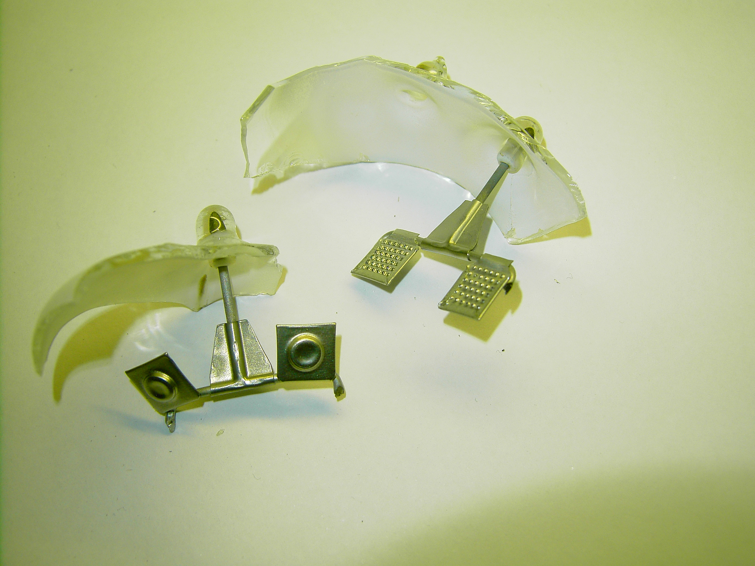
This shows the huge getters from the side. I do not really know what getter material this is, but it is the older very dark getter, as in many tubes from the 1940's. There is always a relation between the getter material, and the rest of the tube. Like when a getter is known to be less active, it means the tube has to be cleaner, and out glowed longer. Such tubes, for that reason have often better long time storage capabilities. |
But it does not allow the grid to move (in this picture) horizontal, which would compromise tube data. Since the grid may not bas attached very stiff to the mica, to avoid microphonics, it van be seen they left (appr.) 0.05mm space between grid bars and mica. This is intentional. |
|
There is an interesting reason behind this. This is a medium gain tube, so not like 45 or 2A3. which are low gain tubes. Low gain tube have less distortion by itself. Higher gain tubes however tend to have more distortion, but there are way to partially overcome this. The beginning and the end of the heater wires, naturally are colder, and these ends have less emission. This would contribute to distortion. However by putting a grid around these positions, and leave the anode away there, this (distorting) part of the filament becomes unused. So electrons can not pass the grid without sufficient positive anode voltage. But there is no anode there at all. On the other hand, leaving the grid away there as well, would again allow (without grid) this a flow of electrons to the anode.
|
|


 There is a similar construction with the Emissionlabs 20B, which is like a large RS242. This is a 20x gain tube, and the grid wires covers the half-warm part of the filaments, to deactivate their non-linear functioning.
 How to judge condition of RS242.
You can hardly see the use condition by the optics. Worn out tubes can look like new, and NOS tube can look dirty, when the boxes have gone missing after 75 years now. What counts is not test reports on Emission Testers, even when the Funke do a good job saying if they 'work good' or not. To judge if they are NOS, is something else.

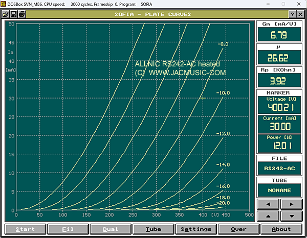
This is a test result with the Sofia tester from 1995. Nicely AC Tested, so not to get errors from DC testing.
As you can see, this tube matches exactly the test point of 400V, 30mA, the -12V curve must cross through there. I have moved the cross hair there also, which means the test data in the right field relates to 400V, 30mA. This tube tests like NOS, and as you can see with good margin in Gm, it has to be 3.0 but this tube tests at 3.57. This boosts up the emission result a lot.
To find this emission, go this way:
- Use AC heating (This test will NOT work with DC heating)
- At 400V Anode, set plate current for 30mA, and write down grid voltage Ug1 needed for this.
- Measure Gm at 30mA.
Now, Emission is calculated as: Ug1 * Gm *2.77
NOS may not be lower than 100%.
This factor 2.77 is specific for RS242 only.
WIth the specific tube which was tested here, we find from the chart: Ug=11.8V, Gm=3.57
This results in Emission of : 11.8 * 3.57 * 2.77 = 116%.
Designing with the RS242
I can not quickly tell here, how to design an amplifier, just mention here the limits and areas of proper use. I remember so well the words of Roger Modjeski, with whom exchanged on many occasions thoughts about amplifier design. He always pointed out to me, use a tube in a none intended way, sounds intriguing because people expect new things from it. However, more likely, known problems will result from it, such as hum, distortion, noise, low Effiency, and reliability issues.
What does this mean for RS242? It is not as low impedance as a 45, but for that is has some other merits. The total package of electrical properties must be seen in combination. When used the right way, the RS242 can easily compete with any other good tube, in a good design. Even when not low a impedance tube, the data sheet allows even 70mA.
Pre Amplifier Application. Suppose we use the RS242 from a 250V DC power supply, as a pre amplifier output. In that case, the 12 Watt dissipation would allow appr. 50mA bias current. This would bring the tube in a lower impedance part of the tube curves, so where voltage is low, and current is high. This is possible, and it is done, when output signal swing doesn't have to be very high, such as inter stage of pre amplifier output. For a pre amplifier output, you need to use a transformer with windings ratio of appr 12:1. This will result in a gain of 1.5x and at the same time bring down the output impedance to appr 32 Ohms. It is so amazingly low, you can connect the volume control directly to the output. (Where it belongs!). This way, hum and noise coming from the tube is already attenuated a factor 12. But, at a gain of 1.5 you won't need full volume. So you will put the volume control at -say- 10% only, and attenuating noise by another factor 10, so a factor 120 in total. Needless to say, such a pre amp will be dead silent, and virtually free of tube microphonics, as this is also reduced by a factor 120.
As an output tube, the target is another. Here, we want maximum possible voltage swing, and (unlike a pre amplifier) the output is now also loaded with a current. The user wants a certain number of Watts from the amplifier, and with only 12Watt tube dissipation, the question of tube efficiency comes in the game now too. The intention of these notes here, is not to produce an RS242 amplifier, but some basic information we can give. A medium impedance tube, like RS242, in order to have good efficiency should be used as such. Medium impedance means high voltage, low current. Just take the highest voltage the tube is made for, it is 400V. At 12 Watt, this means 30mA bias current is as high as you can go. Not going to the tube's limits, would be 10 Watt dissipation, and we have 25mA Bias. A brief look at the tube curves gives some 340V peak to peak would be possible that way. Depending on the output transformer choice, this can give some 1.5 or 2 Watt.
With an appropriate driver circuit, you can drive the RS242 into positive grid voltage, because as a transmitter tube, this would be allowed. This is specialists work, and it requires a very low impedance driver tube. Some say, this makes 4 Watt possible, but I have never tried this.
The Allnic RS242
Allnic is a Korean company, who made their own RS242 for some time, using it for their own pre amplifiers. This tube is indeed an amazing achievement, given this is an amplifier company who decided to make their own tubes. A tube building company, building also amplifiers, we have seen that before. But an amplifier company building their own tubes, that is at another level. At this moment however, they do not build tubes any more.
The data of the ALLNIC RS242 measured here, show it is a very nice tube, with interesting ways to use it. However as you can see from this table, tube data is quire different from Telefunken. Though the Allnics is wonderful tube, it is not a replacement for Telefunken RS242. The Allnic has higher gain, even at lower Rp, which is quite an achievement, but this comes on the cost of more distortion at high signal. As you can see from the table, the Allnic has significantly lower Ug, so the maximum allowable grid signal is lower. (Peak value 11.7 with TFK, vs 8.3V of the Allnic). With the higher gain of the Allnic, this is still possible to do, but at high signal, this will take place at much higher distortion. We need to know, Telefunken never intended RS242 as a pre amplifier tube. However for that, the Allnic seems much more suited, as gain is much higher, and distortion in the grid voltage range of -4V is really very low. So the main difference between the Allnic and the TFK is, the TFK is better suited at an output tube, and the Allnic is a better pre amplifier tube. So as you can see, given these significant differences, these are much different tubes, but in the same family. To my opinion, the part number RS242 should not have been used, but more something like RS243, to indicate the difference.
RS242 @ 400V, 30mA. AC heated. |
||||||
|
|
Gm |
Gain |
Rp |
-Ug |
Remark |
Telefunken |
Specified |
3.00 |
17 |
5k7 |
12.7 |
Ug constructed by pencil in 400V curve. |
Telefunken |
Tested |
3.57 |
16.9 |
4k7 |
11.7 |
Note: This is just a random (NOS). This tube is fine, but it is not a bogey tube |
Alnic |
Tested |
6.79 |
26.62 |
3k9 |
8.3 |
|

RS242-Spez is a version with UX4 socket. This chart was made with DC Heating.

This chart was made with DC heating.
Note the excellent linearity of the EML tube. Even in the very difficult part of high voltage, low current, the curves are near perfect. Compare the range of 450Volt/ 2mA with the Telefunken. With the EML there is still a well separated curves. With the TFK the curves all begin to touch each other. This is a working point which is not used anyway, so by itself this is not a issue. A good designer will never place the load line in this area. It does however at a quick glance tell something about expected distortion at other working points as well.
SPICE Parameters of TFK RS242
These can be used with LT-Spice freeware. In Spice, you draw the circuit first, and then the program can simulate it electrically. If you are new with Spice, follow some of the youtube tutorials.

Conclusion:
RS 242 is a really fantastic tube, and we can understand the high interest by DIY users all over the world. The Telefunken are rare, but when you feel ok with good used tubes, you can find them. Virgin NOS, has a price of course, but you must see, these were made 75 years ago in war times, in Germany, and were not been used ever since. I see little logic in turning pristine NOS into "fine, used" tubes yourself, while you can buy "fine, used" tubes for half of 1/3 of virgin NOS prices.
(C) JACMUSIC. Since 1993. All rights reserved. Copyright note