Testing coils of a Lundahl transformer
There are moments where you want to know the real, measured inductance of a winding, or if windings are open or shorted. However, this needs to be done often in a special way, to prevent transformer damage, and also to prevent getting wrong test results. Both can happen quickly!
1) Measuring inductance.
This is something else as testing for open coils. The more iron a coil has, the less it can be tested accurately with a small signal. You should not measure a coil with the smallest possible signal, but with the largest possible signal. So these tiny little devices which work on a 9V battery, or worse even, from just a few Volts via USB, are only useful for tiny little chokes. For chokes with massive pieces of iron, any small signal tester produces a massive error. Even when they claim to be capable of measuring 20 or 200 Henry, they are definitely not.
BIG transformers and power supply chokes should only be measured at their maximum allowed AC voltage. With less accuracy, but not impossible, use a a lower AC voltage, but it must be in the range. So you can measure a 400V AC coil with 230V, the result is reasonable. Just apply the maximum allowed voltage, measure the AC current, and you can calculate the inductance from this. This is a simple and correct measurement. Lundahl does it just that way in the factory.
Measuring small tone transformers with an LCR Tester is something else. These can be measured with an LCR tester, when you know how to avoid the LCR tester using DC current, AND when it works with large enough signal. These are the two thing you need to know.
However cheap universal LCR testers, start with a DC voltage, or a DC current, to "see what happens". Well, and when 1mA flows, it is already too late for your amorphous core, it is already magnetized. Such testers can NOT be used.
The table shows a clear correlation between the voltage applied to the primary winding and the measured inductance. Tested device: LL1663-PP. These are not "different ways, to find different results". These are all wrong methods, apart from the last.

2) How to test for an open coil.
Do not interrupt the current of an unloaded transformer.
Once you damaged your first transformer by this, or damaged your test instrument, it is too late for this advise.
Why this happens.
At some point, most people shorted a charged capacitor. It will try to maintain it's voltage, and will supply whatever current possible, when you short it. With a chokes something similar happens. A choke with DC current through it, is also "charged" with energy. Same as the capacitor is charged with voltage, a coil is charged with current. The coil will use this energy, to maintain the DC current, even when you suddenly insert a high resistor in the circuit. (or open it) . Do you have 1 Ampere? Just insert 100 Ohms, and the current will keep on flowing. Of course not very long, because same as with the capacitor, the energy of the choke will be absorbed by the load. (100 Volts.... across 100 Ohms... is 100 Watt). But what if you insert 100k or even an open contact? At first the voltage will ramp up very high, in a hopeless attempt to keep the 1 Ampere flowing, and then at some 10 or 20kV, the air ionizes, which means the air becomes conductive. Once conductive, it will spark, and sparks are very low impedance, close to a short. If there was such a spark, this MAY have saved the transformer, because the spark is where the stored energy went into. It was less good when there was no spark, though this may have looked better for the observer. Without spark however, the energy was absorbed by the internal isolation, which is now unreliable. Such pre damage, means trouble at a later moment. With an output transformer for instance, such will have high frequency loss, or efficiency loss.
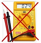
On a much lower scale, something bad happens, when the DC resistance of a tone transformer is measured. All Ohms meters work with 1mA DC, apart from some (very rare and perfect) analog meters working with 100uA, or impedance meters, working with small AC tone signal. So take any random Fluke, or other digital multimeter, and these always work with a 1mA DC current source to begin with. If that creates too much voltage, some meters switch to 100uA, but then it is already too late, and the core is magnetized.
It is a real eye opener, to try this out with two multi meters. Set one for 1mA DC current, the other for resistance, and just connect them to each other. You will see now, the meter that was set for resistance, sends 1mA into the other.
If you magnetize the core of a tone transformer with an ohms meter, the sound of the transformer may become bad.
That is because this pre-magnetism can indeed be so high, the core works not in the undistorted area any more.
This applies for all transformers without DC capabilities. That is either the Lundahl PPZ series for parafeed, or the miniature ones, in the white shielded housing, which by default have almost no DC capability.
Single Ended transformers by nature have DC capability. Also the Lundahl Push Pull tube transformers, and (yes) the Lundahl Mains transformers have enough DC capability to withstand an ohms meter.
 You should better not buy a tone transformer from private sellers on Ebay. We don't need to say here what they will do, when they already did measure the coils, unknowingly, or find out later this was wrong to do, and in any case, the sound is not good. Most specially IF the sound is not good, it is a reflex to start to measure the coils. Either to look for open coils, or wrong connections. If I would not know, it would probably be the first thing I would do myself also.
How can only 1mA damage a transformer?
A tone transformer usually has high inductance, which means many windings. Like many hundreds. For a transformer core, it is the same when little current flows through many windings, or high current flows through little windings. Magnetism results from Current x Windings. So 1mA though 1000 windings is the same as 100mA trough 10 windings. Moreover, this magnetism is concentrated into this tiny little core. So locally, per square centimeter, the flux density becomes too high before you know it.
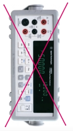 Now I have done some investigation about what most multi meters do. The result is bad. No matter if you have a 8$ DMM from China, or a 1500$ instrument, they all work the same. The software of those is TERRIBLE. All of them. (No... not all of them.... my Metrix MX573 is good). The problem is, they detect "low resistance" when you connect a transformer winding. Then, the logic response is, pumping 1mA DC current through the "Resistor" and see what happens. So they try to become a 1mA current source. This will work very nicely with a coil connected of course. So the meter charges the coil with 1mA. What happens when you disconnect the meter? The coil will now generate a very high voltage, attempting to keep the 1mA flowing. It can be several hundred volts. You are lucky when the meter can withstand that on Ohms setting.
But let's stay with the 1mA test. That's what all DMM on auto range begin with. All you see is the digits move for a fraction of a second, and when it stops you read the value. Then, the meter has already damaged the transformer.
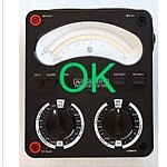 With an analog multi meter you are safe, as they cannot change something to the choice you make, but then you need to choose the highest impedance range, and you need to check FIRST what the test current is, by using a second meter.
A trick
There is however a trick to measure DC resistance with a cheap multi meter. All transformers have multiple coils. Just connect two identical coils in anti-parallel. This will give no magnetic field in the core. You will measure 1/2 the resistance of course, and you can verify it versus the data sheet. In case you measure NOT 1/2 the resistance, it means one coil is open. You have now magnetized the core, but with an open coil, it is scrap anyway. Do this measurement only with wires soldered on the transformer. Do nut use crocodile clips, or other, because one small scratchy contact will be the end of your transformer.
We recommend the following:
- Avoid a digital meter. Such a meter can damage when you try to measure resistance of a coil. Also, such meters use 1mA DC current, to measure unknown “resistors”. This is too much for “AC-only” Audio transformers.
- Never measure resistance of an amorphous core “AC-only” Audio transformer.
- An analog ohms meter can be used for non-amorphous core transformers, when set on 1 Meg Ohms or higher. You cannot accurately measure the DC resistance this way, but you can measure if you have a open contact. Any setting below 1Meg ohms, do not use it.
An Exception is an amorphous core transformer with DC current capabilities (Air gapped transformers). These can be tested with a analog ohms meter, also on low resistance setting.
REPAIR PROCEDURE
In case you magnetized the transformer, there are two repairs possible.
- Just use it, and after long enough time, magnetism may eventually reduce. Some call it burn in, and report improvement after long enough use.
- Use the highest impedance winding. Connect this transformer to an oscillator, and put a multi meter in series, set for 1mA AC current. Begin with high 100Hz, zero voltage. Then increase the voltage to the transformer's maximum rating. AC current should be very low.
- Then lower the frequency, below the limit the transformer is made for. (See note*) Do not go lower as you need. At some low frequency, the AC current begins to rise. Stop at 1mA. This will now saturate (magnetize) the core in the AC rhythm of the frequency. It is not needed to keep it here for a long time. Now, VERY slowly raise the frequency to 100 Hz again, and when you are at 100Hz, reduce the voltage slowly to zero, and you're done.
- No guarantee this repair works. It was recommended to me by a transformer specialist, as a method to repair a magnetized tone transformer. This is on your own risk.
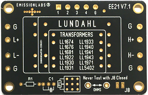
The above is a picture of the universal board EE21 Version 7.1 It suits many of the larger size, four coil transformers, such as LL1674, LL1691, LL5402 and many others. It has many options and possibilities. One of those is a test option for the Resistive termination. As you can see from the text on the board, you need to open the solder jumper J8, before doing an Ohms measurement. This disconnects the transformer from the board, to PREVENT DC damage of the transformer, by the multi meter DC current.
*Note: a very low frequency signal, at some point may be regarded a slowly changing DC signal as well. When the AC current begins to rise, you are in the transition from AC, to a slow changing DC signal. At a much lower frequency, also the AC meter will stop working, unless it is RMS, which can go down to DC. So when you see the AC current begins to rise, stop there.