Electron Engine ™
Printed Circuit Boards by Emissionlabs
EE80 ventilation Adapter with status LEDs
The order number is for the PCB, with LEDs and SMD resistor.
Description
These EE80 air ventilation adapters are compatible with the Yamamoto sub plates. Outside dimensions, appearance and mounting is the same. We have one to replace the original Yamamoto 30mm sockets, one which is 31mm, for some Chinese sockets, and one which is 27mm Version for some vintage sockets. All of these have 38.2mm screw hole distance.
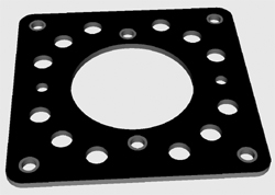
Air ventilation adapter without the LEDs mounted.
If the status LEDs are not wanted, just solder them out, or order the boards without LEDs. Like this, the sub plates will look the same as Yamamoto.
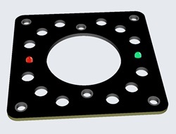
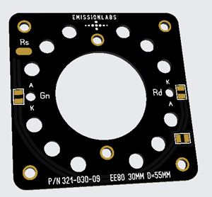
Air ventilation adapter with the status LEDs mounted.
The Red "Alert" LED is normally off, and begins to burn bright if the anode current exceeds the pre set value. The green LED burns analog with the plate current, Indicating the function.
Functioning
For electrical function, the board has a ground connection via the chassis screws already. To operate it has only one input. To this input you need to connect a small resistor, with it's other end to the auto bias resistor. This is all it needs, and the board already works.
The external resistor determines threshold of the red LED. Below the threshold, the red LED is off. Above the threshold it begins to burn bright. Even when the red LED is off, the green LED just indicates analog the tube current.
Available socket diameters:
Order nr: 321-027-17. EE80 for 27mm vintage sockets. Such as the EDISWAN NOS Loctal TEFLON socket.
Order nr: 321-030-09. EE80 for 30mm sockets, STANDARD dimension.
Order nr: 321-032-88. EE80 for 32mm sockets, with wider flange as normal. Some (not all) Chinese sockets have this.
The "alert" limit can be set from 10mA to 300mA. The Board has 10x over capacity. So it is virtually impossible to damage it, because no tube can do 10x it's rated current.
The board has a metal ground plane at the upper layer, which is connected to the mounting holes and to the mounting screws of the tube socket as well. Like this the cage of the amplifier stays shielded against hum fields. You can not see the metal ground plane, because there is satin black paint over it.
How to use EE80 boards:
- For amplifier tubes, the LED function can only be used with auto bias circuit. For the series Resistor Rs, 1/4 Watt is more then enough.
- For rectifier tubes, it can be used to warn for too high voltage of the power supply Such situation may occur if power tubes draw not enough current. This failure condition can damage the power supply capacitors. For the series Resistor it needs to be more than 1/4 Watt, this is explained in the next text part.
The following is an EXAMPLE of how to add these boards to an amplifier
In this example we have a classic 300B auto bias circuit. The rectifier tube is not shown in the schematic, which is not needed, because EE80 senses the high voltage directly. For your safety, please note, the voltage drop is
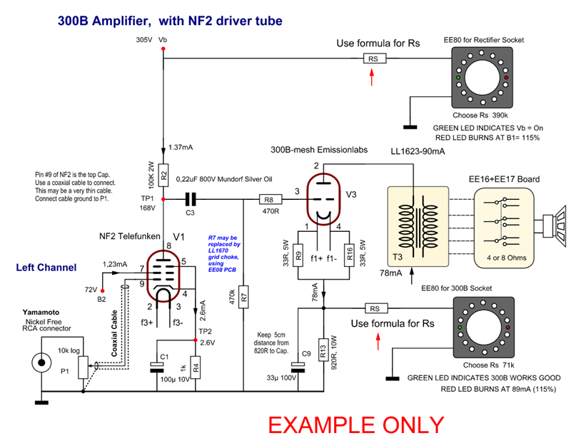
The programming resistor is calculated as follows:
Rs = Cathode resistor x (Cathode current -1mA) |
Calculation Example:
- Cathode Resistor of the tube: 680 Ohms.
- Tube current 50mA.
- We have to take the tube current, minus 1mA. So we get 49mA..
Rs = 680 * (50-1) = 680 * 49 = 33320. Choose: 33k
Some tube examples:
Tube |
Bias Voltage |
Bias Resistor |
Series Resistor (Rs) |
Red LED |
Red LED |
Red LED |
2A3 |
45V |
750R |
44k |
60mA |
72mA |
80mA |
45 |
56V |
1550R |
54k |
36mA |
43mA |
48mA |
300B |
45V |
750R |
44k |
60mA |
72mA |
80mA |
300B-XLS |
88V |
880R |
87k |
100mA |
120mA |
132mA |
520B-V3 |
91V |
758R |
90k |
120mA |
144mA |
158mA |
Possible range of use for Auto Bias tubes
- Tube current from 9mA...200mA and bias Voltage above 15V.
Does it work below 9mA or below 15V Bias?
In many cases yes. Just at Bias voltage below 15 Volt, the formula gets somewhat unprecise. That does not mean it does not work, you just need to find the best value of Rs experimental. Doing so, the circuit works down to bias voltage of 3V.
- This circuit uses always 1mA DC current, regardless of the amplifier resistor or bias voltage. You can try it with the above example, bias voltage would be: 50mA*680Ohms=33Volt. Then, from 33Volt and Rs=33k, the circuit draws 1mA. This current adds up to the plate current. For larger tubes this is no issue, but for smaller tubes, you need to choose the plate current 1mA lower.
Here is a tested example:
Bias Voltage |
Series Resistor (Rs) |
Bias Resistor |
Red LED |
Red LED |
Red LED |
Tube |
3V |
0 Ohms |
680R |
17mA |
20mA |
25mA |
C3g |
Monitor a power supply voltage
This is only possible when EE80 is electrically connected to a metal chassis, and the power supply is grounded to the chassis as well. Choose the red LED such that it stays off when the power supply works good. In that case, the green LED will burn.
Too high power supply voltage quickly happens, in case of an output tube failure, or bias adjustment mistake. In such a case, the capacitors could damage badly. So a continuous monitoring is always a good idea. With the use of the EE80 adapter it needs only one resistor.
Roughly for power supply use, Rs calculates as:
Rs = 1250x Power Supply voltage |
Calculation Example for Power Supply:
Power supply Ub = 305V
Rs = 1250 x 305 = 381k / Choose 390k.
Rs Dissipation = (Ub*Ub) / 390k = 0.24Watt / Choose 1 Watt
To adjust it precisely, wait until the amplifier is all ready and finished. Then initially find a value for RS at which the red LED is just beginning to burn dim at normal condition. After this, use a Rs value which is 15% higher. Now, the red LED will be off, and the green LED will be on, showing the power supply voltage is correct.
Back side. The series resistor Rs is connected, with one side to the Rs solder pad. The other side is connected to the auto bias resistor of the circuit.
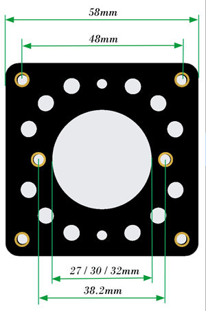
Dimensions: .
Order nr: 321-027-17 (27mm hole)
Order nr: 321-030-09 (30mm hole)
Order nr: 321-032-88 (32mm hole)
Recommended chassis hole:
D=55mm