Electron Engine ™
Printed Circuit Boards by Emissionlabs
EE60 Universal Experimenter PCB
This is the OLD Version, inly for reference here for users. New version is here.
WE SUPPLY ONLY THE BARE PCB.Tube sockets can be ordered with it.
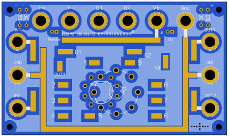
Board Order Number: 310-033-72
Originally I made these PCB for myself, but it is also a nice product to sell. It reduces the mess on the bench very much.
- Double Sided PCB with ground plane at each side. Size 13x 8cm.
- Can be used for pentodes or double triodes.
- Use a 9 Pin noval socket, or 8 Pin Octal or Loctal socket.
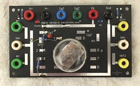
- Connect low cost Chinese banana plugs to the board, or just solder wires directly.
- CONNECT THE HEATER: At the back side are solder pads, which you can use for some permanent components, and permanent connections. In any case these are the heater pads. Look at the picture below with the green wires. This is for 6SN7, it needs the heater at Pin 7+8. By this method, the top side of the PCB becomes less messy.
- CONNECT THE Ug1 and Ug2 PADS. Probably the ones you experiment most with. Also these have pads at the BACK SIDE. So with little wires, connect those pads to the tube. For 6SN7 that is Pin 1 + 4. The Ug1 and Ug2 pads at top side, are through-connected to the back. So the front side stays easy to use. The banana jacks Ug1 and Ug2 are also connected to those pads. So via the banana plugs, you can measure, or use those for input / Output.
- The signal plugs (IN and OUT) have the right distance to connect a banana to BNC adapter to it. (See below)
- The High Voltage (Vb) has a blue warning LED, so you won't get zapped any more by mistake when the High Voltage is on. I appreciate this myself :)
- The heater has a red warning LED, which burns at AC, or DC. When heated DC it burns only when the heater voltage is connected the right way.
- FOR each amplifier stage, use it's own board. You will like this system!
Wiring one half of a 6SL7
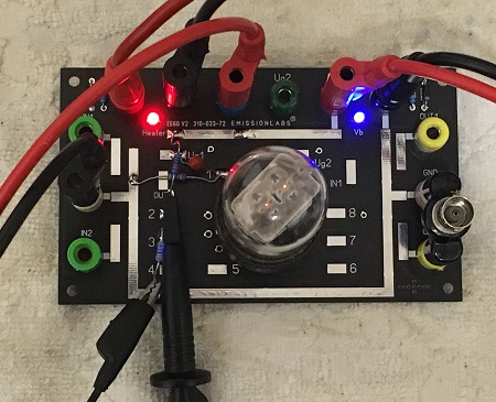
Testing
The distance of the In-1, In-2, Out-1, Out-2 to GND, i is such that you can plug in a standard banana/BNC adapter, as shown above in the picture.
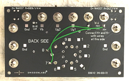
Connecting the heaters:
Also it is possible to connect Ug1 and Ug2 directly to the grids, and measure at other side of the board, via the banana jacks, what the grids are doing. This is probably the most common way to attach the grid. For the input, use the pads (In-1 and In-2 at the other side), and from there wire it with a capacitor, or whatever the circuit is.