Since 1993 Copyright Notice
Electron Engine ™
Printed Circuit Boards by Emissionlabs
EE40 Universal HV Power Supply board for rectifier tube, or silicon diodes.
Kit order Number: 311-040-39
MOST PARTS ARE INCLUDED. You receive:
- PCB EE40 (Size 13 x 10cm) with following parts included:
- Octal Socket, 5x rectifier diodes, blue LED, 2x Fuse holders, High Voltage Capacitors 2x 350uF. Resistors: 2x 470k, 2M2, 1Ohms.
- Not included: All other parts.
Have you ever noticed, some amplifiers are totally free of hum, with a relative simple construction, while some others, build expensive, with huge capacitors and big effort, just keep on producing some residual hum?
You can hardly calculate a tube power supply. What you get may be near what you wanted, but it often needs quite some trial and error still. However with a high voltage power supply, a messy set up is dangerous, and you probably end up with another grounding scheme in reality, as on the drawing.
This is where the EE40 is helpful. It helps to find out the ideal circuit, and it can even be used as a final PCB.
There are many cases where hum ist generated by unlucky wiring, and people don't realize. Then to deal with this, capacitors are oversized. This helps, but not completely. While the over sized capacitors cause other problems, like tube sparking. Also excessive capacitor charge peaks will radiate hum and it's harmonics into the pre amplifier. Just via the air.
The basic design rule has always been: A low voltage power supply needs a large capacitor and a small choke. A high voltage power supply needs a small capacitor and a large choke. If oversized capacitors must compensate a small, cheap choke, it is not just violating the rectifier data sheet. It is asking for trouble. It gives electrical and mechanical hum, and it wears out the rectifier tube too fast. However, because it costs less, you find this often in commercial products. |
We encourage you to use the Lundahl high inductance, dual coil chokes (they have only such types), for which the PCB is prepared. There is no obligation to use them. Also a single coil choke of your own choice can be used.
For the rest, please be not confused by the long texts below here, because EE40 is easy to use.
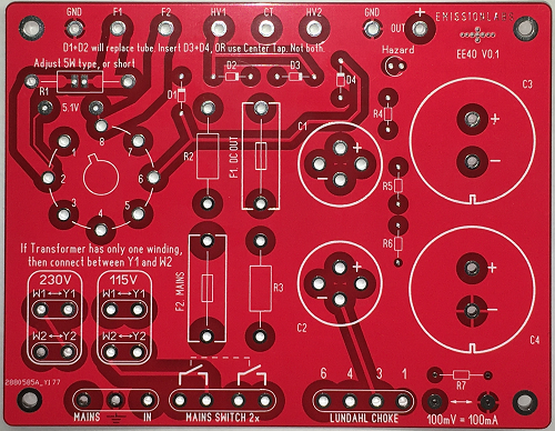
Board Dimensions: 13.2 x 10.1 cm. Power Supply Boards are RED. Tube boards are BLUE
There are two ways to use EE40
1) Evaluation board on the bench. In this case, the tube socket is mounted together with all other parts at the components side.
2) Final board in an amplifier, with the tube socket mounted on the PCB. In this case, the tube socket will be mounted on the BACK of the board, so tube is plugged in at the solder side. However the socket has to be mounted in another position. This dot, you have to align with the center slot of the tube socket.
Please note: Close the solder Jumpers across R1 and R8, if you are not using those resistors. Otherwise the PCB will not work.Features:
- Rectification: Use silicon diodes, or tube likes 5U4G, 274B, 5Y3, GZ32, GZ34, 5AS4, 5AW4, 5AX4, 5AZ4, 5R4, 5T4, 5V3, 5V4, 5W4, 5Y3, 5Z4, 83, 83V, AZ31, AZ32.
- MAINS Part. All mains circuitry MAY be done via the board. This is not required, but it reduces your high voltage wiring.
- In case you use the mains primary connections of the PCB:
- If the transformer has one mains winding of 115V or 230V. This is connected to Y1 and W2 of the according 115V or 230V pad.
- If the transformer has 2x 115V primary. For 115V mains, connect those two windings to the 115V pads. Or to the 230V pads to connect to a 230V mains. W1-Y1 is one winding, W2-Y2 is the other winding. It doesn't matter how they are called on your mains transformer, but mind the polarity of the windings on the PCB: W1 and W2 have the same polarity.
- Tube HEATER: There is the option to add a small series resistor to adapt the transformer voltage exactly to the tube. If using smaller tubes such as 274B or 5Y3, on a higher current 5V winding, voltage may rise above 5V. There is a solder bridge to short this series resistor, if not used. On the PCB are measurement pads for quick testing of the heater voltage.
- Transformer HV windings resistance. All rectifier tubes require ALWAYS a minimum copper resistance of the high voltage winding. There is no exception to this, and it is the #1 mistake to ignore this. Leading to short rectifier life. Designers are surprized this requirement exists, and today's transformer winding companies do not know about it any more. However, the minimum transformer DC Resistance, Rtr, is specified in all good rectifier data sheets. if the transformer copper resistance is lower as in the data sheet, the tube may spark at switch on. When there is no spark, that doesn't automatically the situation is ok. Also In this case, a series resistor needs to be used. More about this here
- Lundahl 4-Terminal dual coil: In case you use these: PCB numbering = Coil pin numbering.
- Normal 2-Terminal coil. Apply a wire bridge from 6 to 4, and connect the coil between 3 and 1.
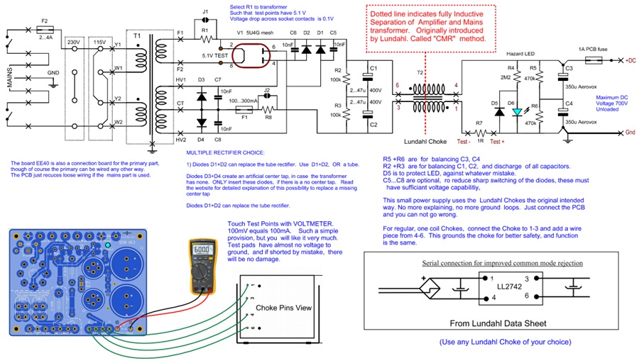
- Test Pads to measure Output Current. A resistor R7, with value of 1 Ohms can be put in series. With a VOLTMETER, current can be measured. 100mV equals 100mA. Such a simple provision, but you will like it very much. This resistor is in the ground path, at a place where it has no high voltage on it. Also it is not in the impedance path of the output capacitors. If you don't want to use this option, solder a wire piece in the place of R7.
- Diodes D1...D4. We supply 4x 1N4007. PCB holes allow also higher quality "glass pearl" type diodes of your own choice. Do not mount all four diodes, unless you want this. Tube rectification requires two, or no diodes, depending on the scheme. Silicon diode rectification requires two or four diodes. (Options are in the table below)
- Capacitors C1, C2. These are not used for a pure L-C design. In that case, you could however still add small values here, like 1...5uF, to adjust the DC output voltage. In that case, these should have a good AC current specification. Otherwise they would get warm.
- Capacitors C3, C4. For Electrolytics, maximum voltages of normal types stop around 500V. When experimenting with the circuit unloaded, it would raise the output voltage a lot. So one single 500V capacitor is too dangerous. For this reason, to allow 700V unloaded, we have connected two 350V capacitors in series. Beware not to exceed this 700V, with the transformer of your choice, in unloaded condition.
- Capacitors C5...C8. Some people like using those, to reduce sharp voltage spikes, when silicon rectifiers are used. You see that sometimes also in vintage circuits.
- Load resistors R2 and R3. Provide the discharge at power off, this helps to prevent tube sparking. These are 1 Watt types, in which we dissipate 0.8 Watt with an unloaded EE40 board. Resulting in appr 0.6Watt if the output is loaded. The value of one resistor = 0.5 * (specified transformer voltage)^2. Example: With a 450V AC transformer, we get R2=R3=0.5*450*450=100k. If voltage doubling is used, you have to calculate with 2x the transformer AC voltage. Even when not using capacitors C1 and C2 (like when using an L-C filter) R2 and R3 should be applied, in order to achieve a minimum load. This minimum load will take the peak off the unloaded voltage.
- The balancing resistors R5 and R6. These are only for balancing the output capacitors. These are 470k, 1/4 Watt. The capacitor discharging of C3 and C4 will take place mainly via R2 and R3, via the choke. The blue LED indicate if the capacitors are charged, which can sometimes be surprising, also in case of remaining voltage switched off.
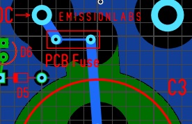
- Fuses. The mains fuse, F2 is for emergency. The fuse F1 is for output overload. There is also a PCB fuse, which is will blow out when the capacitors are shorted by a stupid mistake. It happens.... This is just a thin PCB track, which burns out, and prevents total PCB damage. In case this happens, you need to bridge this position with a very thin wire piece.
- Power supply boards are red color, amplifier boards are blue color.
- Blue Hazard LED. Prevents painful mistakes :)
Rectifier configuration |
|||||
Rectifiers type |
Transformer has center tap? |
Voltage doubling used? |
Silicon diodes mounted(do not mount more diodes) |
Example for 250V AC. (DC voltage depends on load) |
|
1 |
Silicon Only |
Yes |
No |
D1, D2 |
250-0-250 primary will give appr 300V DC. R2=R3=31k. Take closest commercial resistor value. |
2 |
Silicon Only |
No |
No |
D1, D2, D3, D4 |
250V primary will give appr 300V DC. R2=R3=31k. Take closest commercial resistor value. |
3 |
Silicon Only |
Yes, but this wire is NOT connected to the board. |
Yes |
D1, D2, D3, D4 |
250-0-250 primary will give appr. 600V DC. R2=R3=125k. Take closest commercial resistor value. |
4 |
TUBE Only |
Yes
|
No
|
none |
250-0-250 primary will give appr 300V DC. R2=R3=31k. Take closest commercial resistor value. |
5 |
HYBRID Click here for notes |
No
|
No |
D1, D2 |
250V primary will give appr 300V DC. R2=R3=31k. Take closest commercial resistor value. |
6 |
HYBRID Click here for notes |
Yes, but this wire is NOT connected to the board. |
Yes |
D1, D2 |
250-0-250 primary will give appr. 600V DC. R2=R3=125k. Take closest commercial resistor value. |
Filter configuration |
||||
Type |
Choke Type |
Wiring of connections |
Note |
|
1 |
C-L-C |
Single Coil |
Choke at 1-3, Wire Bridge from 4-6 |
This will keep coil at ground level for more safety. |
2 |
C-L-C |
Dual Coil |
Lundahl choke, pin numbers equal 1-3 and 4-6. |
Lowest noise |
3 |
C-R-C |
Resistor from 1-3 and from 6-4. External Resistor, with cooling. | Has residual AC. Possible for Push Pull with feedback. | |
4 |
L-C |
Dual Coil |
Lundahl choke, pin numbers equal 1-3 and 4-6. Leave away: C1, C2, but still use R2, R3 |
Ultimate way, but requires 2...3x larger inductance. Allows highest DC power to be pulled from the rectifier. |
5 |
L-C |
Single Coil |
Wire Bridge from 6-4. Choke at 1-3. Leave away: C1, C2, but still use R2, R3 |
Ultimate way, but requires 2...3x larger inductance. Allows highest DC power to be pulled from the rectifier. |
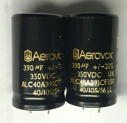 Capacitors C3 and C4 are included. These are 105�C Type.
Please note this: These capacitors are superb quality NOS Audio Capacitors from 1995, made in England, but they should be formatted before first use. This is nothing but a very slow start, for the first time. The EE40 board itself can be used for this as follows: Finish the board, but WITHOUT R4, R5, R6, R7. Connect a resistor of appr. 1Meg at the place of R7. Switch on the board now. The unformatted capacitors C3 and C4, will initially refuse to charge quickly to a high voltage. This is normal, and the output voltage will rise slowly. When the voltage stops rising, the formatting is ended. This can take 5....20 minutes. After this, switch off the EE40 board, and wait for the capacitors to be discharged. Now add R4, R5, R6, R7 to the board, and it should work normal.
Function of the links across R1 and R8.
These links should initially be closed, to get the circuit to work. But later you should decide on the best value for R1 and R8.
R1 is used to adapt the transformer voltage to the tube. The actual voltage can be measured with probes, across the test points "Test Fil". Note, tubes can tolerate only maximum 5%. If the heater voltage is too high or too low, the rectifier may spark at a cold start.
R8 adapts the transformer Raa specification to what the tube needs a a MINIMUM. So when the tube data sheet writes Raa>130 Ohms, and the transformer Raa is 70Ohms, R8 becomes minimum 60Ohms. If Raa of the transformer is too low, the rectifier may spark at a cold start.
In reverse, if the rectifier does not spark, it does not mean R1 of R8 are correct, or not important to look at. Most early rectifier failures are caused by this.
Use of EE40 with some Lundahl transformers
Lundahl transformer |
Transformer Center Tap |
Voltage doubling |
Artificial Center Tap |
DC Output voltage unloaded. |
Maximum Load. |
| HV windings in series. Connect 6 to 8. There no Center Tap. "CT" of PCB stays empty | No |
Yes. Insert D3 and D4. | 490V. See also Notes on this. | 630mA |
|
| HV windings in series. Connect 6 to 8. There no Center Tap. "CT" of PCB stays empty | No |
Yes. Insert D3 and D4. | 322V. See also Notes on this. | 1A |
|
| HV windings in series. Connect 6 to 8. There no Center Tap. "CT" of PCB stays empty | No |
Yes. Insert D3 and D4. | 490V. See also Notes on this. | 630mA |
|
| HV windings in series. Connect 6 to 8. There no Center Tap. "CT" of PCB stays empty | No |
Yes. Insert D3 and D4. | 700V. See also Notes on this. | 43mA |
|
| Unloaded voltage would be 743V, this is not possible with EE40. | |||||
| Connect "CT" of PCB to 22+24 of transformer | No |
No. D3 and D4 are REMOVED. | 350V. See also Notes on this. | 160mA |
|
| HV windings in parallel. There is no Center Tap. "CT" of PCB stays empty | No |
Yes. Insert D3 and D4. | 350V. See also Notes on this. | 160mA |
|
| HV windings in series. There is no Center Tap. "CT" of PCB stays empty | Yes |
Yes. Insert D3 and D4. | 700V. See also Notes on this. | 80mA |
|
| Connect "CT" of PCB to 22+24 of transformer | No |
No. D3 and D4 are REMOVED. | 350V. See also Notes on this. | 260mA |
|
| HV windings in parallel. There is no Center Tap. "CT" of PCB stays empty | No |
Yes. Insert D3 and D4. | 350V. See also Notes on this. | 260mA |
|
| HV windings in series. There is no Center Tap. "CT" of PCB stays empty | Yes |
Yes. Insert D3 and D4. | 700V. See also Notes on this. | 130mA |
|
| HV windings in series. Connect 19 to 22, this is the Center Tap, connected to "CT" of PCB | No |
No. D3 and D4 are REMOVED. | 490V. See also Notes on this. |
200mA |
|
| Voltage doubling would give 980V unloaded, but PCB and Capacitors are not made for this. Not possible with EE40. | |||||
NOTES and some tech talk.
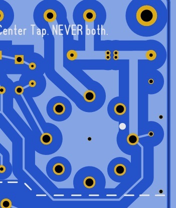
| The strange position of Fuse F1. Before we dig into the virtual center tap, here is why the fuse is at this unusual place. Few people choose this position, but I think there no better place. Most of the time, the fuse is directly placed at the output, but no normal radio fuse can fuse 700 DC (which is the unloaded voltage) safely. Fusing AC, is much easier than fusing DC. If a DC fuse at 700V gets activated, the fuse becomes totally black inside, but there is a risk it may explode so violently, it is completely gone. Even the two metal parts may not be at it's place any more. Sand filled fuses are safer, but I wouldn't bet on what happens if you fuse 700VDC with a 230V AC fuse. That is why we put the fuse in the center tap, which is grounded, and it is at AC level instead of DC. An additional advantage is now, the fuse is at ground level. It's much safer. We do not sell fuses, but when you buy one, make sure it can fuse the AC voltage of your transformers high voltage winding. |
The Artificial center tap. To use a tube rectifier, requires a center tapped HV winding. If this is missing on the transformer, we can still use this transformer, when we create an artificial center tap, with two silicon diodes. Before understanding this, first look at a classic center tapped circuit: The center tap is GROUNDED. This is very important to keep in mind. To understand how the VIRTUAL center tap works, look at the negative of C2 in this schematic This is ground level. We have the choke in between, but it filters out only residual AC before the choke. The virtual center tap would work just as well without the choke. With a single coil choke from 4-6 and a wire link from 1-3, C2 is even hard-grounded. And yes, feel free to try this with the EE40. So regard the negative of C2 as GROUND level, just for better understanding. The fuse F1 plays no role for the functioning of the circuit. To the fuse is D3 and D4 connected, and the transformer has no center tap. Here is how it works: Since we have AC signal, ALWAYS either D3 or D4 is in conducting state. This means, in conducting state there is only 0.7V DC across it. This means at the positive half of the mains, D3 is conducting and the fuse is clamped to ground by the conducting diode. At the other half of the mains, D4 is conducting. So all of the time, the fuse is clamped to ground. The only difference with a real center tap is this 0.7V DC of the conducting silicon diode, but in compare to the voltage drop across the tube rectifier (some 20...35V) this can be neglected. This doesn't change the rectifier tube curve, other than by shifting it up 0.7VDC. As the tube pumps into 400V DC (or so) of C1+C2, this 0.7V plays no role at all. So with the diodes, the tube pumps current into 400.7V and otherwise into 400V. The tube itself has a resistive character, and a current limiting effect for peak current, which is why we use it. This will not be changed in any way. Virtues of tube rectification (less aggressive charge spikes, slow start and current limiting) it stays all unchanged. This way, indeed still normal tube characteristics will stay. |
| Voltage doubling. Another thing we can do with the artificial center tap, is voltage doubling. A 250V-0-250V winding with tube rectification would normally give 300V DC (depending on the load of course). WIth an artificial center tap, voltage doubling occurs, and we get 600V DC. Note: In case of voltage doubling, do NOT connect the center tap together with the diodes D3 +D4. So the center tap must not be connected to the PCB, but D3+D4 must be soldered in, and then you have voltage doubling. Also with a tube rectifier. Correct connections for this, are in the table.. |
| What is a center tapped winding? Under cost pressure, transformer winding companies over simplify this, unless you give clear orders how to do it. Here is why. Because of AC, and because we use rectifiers, a center tapped winding carries only current through one section of course. This would be fine with a toroid, or with any other core, when BOTH halves of the tapped winding are wound TOGETHER, so physically at the same place, and in addition have the same geometry too. This can only be done with bifilar winding, or a split chamber. Bifilar is not possible with High Voltage. A split chamber, you can check if it there, from the outside. Is this not visible, then you don't have it. The cheaper way, the usual way, to lay one package over the other, will lead to uneven wire length, and uneven load, due to copper resistance difference, and uneven magnetic coupling. Effectively this will give some l DC magnetization of the core. Then, at large voltage, this would saturate the core, which gives a specific noise, which you may have heard before. It sounds like "hummmm". Particularly under dimensioned transformers will have no air gap, because air gapped cores cost more, and are larger dimension, even requiring a longer copper wire. Meaning however, under dimensioned transformer can withstand absolutely no DC component. To be on the safe side, such windings should be dimensioned a factor 1,7 larger, is what Per Lundahl told me. Will EL CHEAPO company do this? No, I don't think so. Simply inquire if their center tapped winding balanced (symmetrical) and if the transformer has an air gap. When they dispute the need, or don't understand why you say this, you can already expect what you are getting. Alternatively, for low cost transformers, you should think of the HYBRID connection. This avoids the problems resulting from a not correct constructed tapped winding. |
Raa Winding resistance. Rectifier tubes require always a minimum Rtr, which is ideally the Raa windings resistance. This special knowledge of tube transformer making has gone with the wind of modern times. But for the tubes itself, this requirement has not gone at all. Each rectifier requires a certain MINIMUM Rtr, windings resistance, or the tube will have low lifetime, or even spark at switching on. In classic circuits, transformer Raa can be measured at the tube socket, between the tube Anodes, when the amplifier is off, mains cable and rectifier tube unplugged, and capacitors discharged. In most cases this value is much too low. This major design error can be fixed by adding an external resistor in each side of the Raa winding. This resistor has half the value of the total Raa required. If a tube needs Raa of 250Ω Ohms, and you measure 100Ω only, there is 150Ω missing. So to add this 150 Ohms, you need to serialize two resistors of 75 Ohms at each transformer winding ends. Alternatively you can add one single resistance of 75 Ohms at the Cathode Tap, which has the same effect. Then, from the tube's view you have Raa of 250 Ohms again. So to be sure, unplug the mains, wait for capacitors to be empty, unplug the rectifier tube, and measure transformer Raa at Pin 4 and 6 of the Octal socket. This value is important, it may not be too low, or tube problems can occur, and transformer hum will be too loud also. This simple measurement is HIGHLY interesting to do on expensive tube equipment. Any yes, chances on a mistake is higher than finding no mistake. It is sad but true, and it caused so many rectifier to die too soon. But really, we can not have transformer builders chance the requirements of tube data sheets?! That would be silly. |
| Loaded voltage depends on output current, but it can be lowered, by using very small values FOIL capacitors at C1 and C2, like 1...5uF. These quite some AC current and should be capable of it. Mainly that will be such with large dimensions. Otherwise they have too much internal resistance, and get warm. Or even leave C1 and C2 away completely. This will be on the cost of more AC ripple, which increases with the load. So this makes mainly sense at low current, and you find the loaded voltage is higher as expected. Another way to lower output voltage, is to add series resistors in the HV winding, there will be AC ripple across this resistor, which has two effects. First output voltage will drop, and second, t this AC voltage gets removed from C1 and C2. So filtering will improve also. As a third method you could combine both. So get the initial drop with a smaller capacitor for C1 and C2, and then make fine adjustment with a series resistor. The Resistor for this is R8. This resistor will become hot, and must be an external power resistor. So there are only wire connections for this on the PCB. If not used, the solder bridge must be closed. |
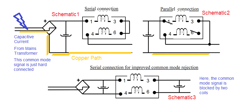
The reason why dual coil chokes are made. Look at the schematic, and you will see how a dual choke cuts the ground path. That is the whole reason for it. The below schematics explain the effect, but is stays difficult to understand immediately
|
FAULT FINDING
| The fuse F2 blows often. The mains fuse F2 should be slow type, and not chosen to critical. Depending on the transformer and the load, start up current can sometimes be quite high. The mains fuse is only for emergency and can be chosen higher as the steady state current. The normal fuse for overload is F1. If the fuse F1 blows too often, this means the choke is too fragile for the job. You can recognise such already by too small dimensions. WIth an oscilloscope, the start up current through the choke can be made visible. Ground it to the PCB, and connect the probe to the 'TEST-Minus' test point. 1 Volt equals 1 Ampere. This should be close to a DC current, since such an inductor can not pass AC current.. Any nasty AC peaks, indicate saturation, which may blow F2. |
| If the fuse F1 blows too often, this means the choke is too fragile for the job. You can recognise such already by too small dimensions. WIth an oscilloscope, the start up current through the choke can be made visible. Ground it to the PCB, and connect the probe to the 'TEST-Minus' test point. 1 Volt equals 1 Ampere. This should be close to a DC current, since such an inductor can not pass AC current.. Any nasty AC peaks, indicate saturation, which may blow F1. If you have no oscilloscope, use a voltmeter to measure across the test points. Check on AC and DC. |
| Rectifier tube heater is not glowing. When there is AC voltage at F1 and F2, but the tube is not glowing, either apply the Link J1 if the transformer is made for the tube, or use a resistor R1, to adapt the heater voltage. If no solder Link J1, and no resistor R1, the tube can not work. |
| Rectifier tube heater is glowing but there is no high voltage. So the blue LED is off. Check if Fuse F1 is good. Was the link J2 inserted? Or otherwise was R6 inserted? If no solder Link J2, and no resistor R6, the tube can not work. |
| The blue LED burns, but there is no DC at the output. The PCB fuse was blown, due to a short. |
A lot of hum on the output signal. If using a Lundahl dual coil choke, you may have connected one of the windings in reverse. AC hum should be almost none. So when there 20V or so, hum signal, this is the reason. With another brand choke, sometimes they are tiny dimensions, but there is no magic. It may by over specified with DC current, but also AC VOLTAGE across a choke is limited, and you need to MEASURE what AC you have across the choke, and compare this to the specification. |