Electron Engine ™
Printed Circuit Boards by Emissionlabs
EE21/23 Gold Plated Board V7.1, for Output Applications
Using LL1588, LL1592, LL1922, LL1930, LL1940, LL1949, LL5402
- Overview
- MC Applications
- Input Applications
 Output Applications (you are here)
- All Connection Schemes, Complete Overview
- Unsorted Application Information
Unfortunately, there is no such thing as standard input signal level for a power amplifier. So to be on the safe side, some designers use 0.25V Input. The manufacturers of CD players, Tuners, pre-amps, also want to be on the safe side, and produce up to 3V Volts output. So effectively, the input signal is too large most of the time, meaning we can use only a small part of the volume knob. On top of that, manufactures of pre-amplifiers, mistakenly think these must amplify the signal, because they are "amplifiers". Like this creating more difficulties, and in the end the sound becomes noisy and sterile, because the volume control must be used almost "cut off" for normal room loudness. All of this for no good reason.
So the solution is simply to use an attenuating output transformer. Thus allowing the pre-amp tube more signal swing, so it develops more tube sound, and signal to noise ratio becomes better too. Like if we attenuate the output by a factor 9, the impedance will be a factor 9x9 = 81 lower. Which is the real reason to use a pre-amp. So from a 2k tube, we get 24 Ohms output impedance. The gain switch (Option3) will allow two signal levels. So a "high" and a "low" output can be created with almost no effort.
1) Low noise Output. Application with LL1940 and EE21
Parafeed in. Balanced or unbalanced pre amp output.
LL1940 looks like MADE for this board. LL1940 is a microphone transformer, but it may as well be used for parafeed.
 Consider tubes like C3m, C3g, D3a in triode mode
This is a very interesting application. So parafeed means the output tube works with a plate choke or plate resistor, and in then capacitor coupled to the transformer. Without having to go into parafeed theory, let's just stick with the conclusion, that this works definitely better than single ended. With parafeed the frequency range and linearity is better. Since it keeps away DC current from the output transformer, we can use these nice PCB tone transformers. No board tuning needed.
The advantage of the 9:1 attenuation is, tube hum and tube noise is attenuated a factor 9 as well. Whereas many tubes have enough gain to compensate this, and the overall gain of tube + LL1940 is still like 3x or similar number.
Gain adjustment
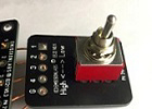 Use of EE22 Board (External Switch). Leaving Jumpers J1 + J3 open, and use the Additional "High-Low" switch board makes it even nicer. Now the pre-amp gets a "High-Low" switchable output. In the table, the switch would make the board jump from Line 2 to Line 5, or from Line 3 to Line 4. The EE22 board is Option#3 from the price list.
Or, of course the "High-Low" option can also be done with a piano switch at the back. This is Option#2 from the price list.
SOME examples. Probably more can be found.
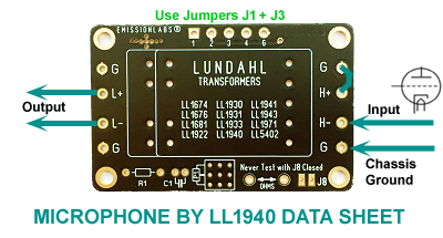
2) Microphone Output LL1940 using EE21
- Connections are as follows, just according to LL1940 data sheet.
- Correction network is not needed
- Only possible with PCB Version 7.1 or higher
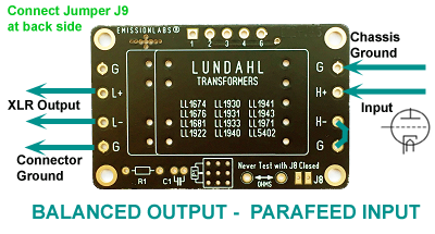
3) Low noise Output. Application with LL1930 using EE21
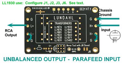
LL1930 is used reversed here. This is an excellent application, it really deserves more attention. By using the LL1930 reversed, it becomes an parafeed (step down) output transformer, also recommended in this application by Per Lundahl.
Parafeed means the output tube is choke loaded, and coupled with a capacitor to an output transformer which works then free of DC current. (Some notes on parafeed)
Since LL1930 is used reversed in this application, the EE21 board is reversed as well. The filter is disabled, by not mounting these parts. What is left is the Jumpers J1, J2, J3, for setting the two possible windings ratios.
Set J1 + J3 for windings ratio 11.6 : 1
Set J2 for windings ratio 5.8 : 1
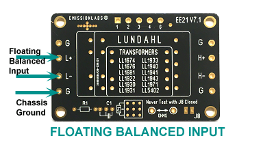
The Input is H+ and H-.
The Output is L+ and L-
H stands for 'High Signal Side', L for 'Low Signal Side.
G is connected to the board ground plane.
The output impedance will be the tube plate impedance divided by 135, with Ratio 11.6 and divided by 34 with Ratio 5.8. So the exceptional low output impedance, output transformers create, will result in a hum free signal transfer. For instance a 6SN7 tube which has a nice gain of 20x, but too high output impedance (7k7) for a direct output, will result in a 57 Ohms output, and yet still provide a gain of 1.7x. Gain is 20/11.6. However this gain of 20x is only achieved when choke loaded. If resistor loaded, a gain of 15x will result, still allowing a total gain of 1.3. Then, if higher output signal is needed, just change to step down factor of 5.8 and output voltage will double. Tubes like E88CC will work even better, due to higher gain and lower Ra. Output impedance will become as low as 16 Ohms, even capable to drive a head phone.
Safety. G must be connected to the chassis, to make the static shield of LL1931 work, and also the shield serves as electrical safety in case of a short between input an output. The metal rings of the mounting holes are also connected to the board ground plane. (Some notes on good grounding)
Floating Output, not center tapped. When the board is grounded properly, the output can be used floating, thus creating a floating, balanced output. For a balanced output, an XLR connector can be used, or an RCA (Cinch) connector with floating ground can be used. Even so, an XLR connector can be wired in parallel to an RCA (Cinch) connector. This is possible with 11.6 and 5.8 windings ratio.
Balanced Output, center tapped. This can only work with output windings in series, so the 11.6 : 1 Ratio. The center tap is connected to Grounded of the PCB by Jumper J3,.
Unsymmetric Output. Connect L- with a wire jumper to G, and L+ becomes the output signal with reference to ground.
Output |
Low Attenuation |
High Attenuation |
Core |
Characteristic |
| LL1930 | 5.8x |
11.6x |
Mu Metal |
Parafeed pre-amplifier output. Low Ra tube. Will not damage from DC component if it happens. |
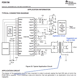
4) DAC Output, Current to Voltage conversion with LL1588
This is an excellent application for a tone transformer.
The DAC has outputs I+ and I- (can be called different) and the current from those must be changed into a voltage. Moreover a high pass filter is needed, and all in all, this requires very complex analog circuitry. A much better idea, is to do all this with just a tone transformer. Mind the following:
- The DAC does not go below 20Hz, but still a small DC-offset may be present. A tone transformer can remove this nicely, provided it can handle small DC levels.
- Whatever unexpected failure the DAC may produce, such as switch on or switch off, there is always the risk on a short moment of DC signal. An amorphous tone transformer can NOT handle any accidental DC level, and it would be permanently damaged by the remaining magnetism.
- Transformers should mu-metal core, can not be damaged by this.
Mu-Metall transformers
Input |
Board |
Low Gain |
High Gain |
Core |
Characteristic |
| LL1588 | EE23 | 1x |
2x |
Mu Metal |
Brother of LL1684, but LL1588 may have a small DC component, for instance with a DAC. Board may also be used reversed, to get attenuation. |
| LL1592 | EE23 | 1x |
2x |
Mu Metal |
Neutral sound, High Signal. Board may also be used reversed, to get attenuation. |
| LL1949 | EE23 | 0,5x |
1x |
Mu Metal |
Neutral sound. Attenuating or 1:1 input |
| LL1922 | EE21 | 4x |
8x |
Mu Metal |
Neutral sound. |
| LL1930 | EE21 | 5.8x |
11.6x |
Mu Metal |
Designed for parafeed pre-amplifier output. |
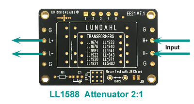
Example with LL1588, 1:1 straight, or 2:1 attenuation.
2:1 is advised when the DAC output signal is much larger as you need anyway. Without going to deep into theory, it should be enough to say this improves the S/N ratio, or from an another view, you are using more bit of the digital signal, at the same volume level. So when the DAC produces 3V at maximum signal, and the amplifier needs maximum 0.3V, consider to use the 2:1 attenuating option. Or completely without theorie: Try it out and decide what you like more.
- For 2:1 J1 Closed, J2 Open, J3 Closed
- For 1:1 J1 Open, J2 Closed, J3 Open
- J5 Closed, J7 Open, J8 Closed. This enables the use of R1 as termination resistor. It's value must be adapted to what the DAC requires. The resistor becomes connected to the DAC output.
- In case you want to play with a variable termination resistor, this is how to do it: Leave in R1 as a minimum value. So you can't short the DAC. Open J5 and J7, close J8, and use a potentiometer P1 of your choice. P1 and R1 are in series now. So when R1=5k and P1=150k, you can change from 5k to 155k.
- Connect I+ and I+ of the DAC to H+ and H- of the EE23 board.
- L+ and L- is the output
- The output L+ and L- are symmetrical (for XLR). To make it unsymmetrical (for RCA connector) the RCA center pin comes to L+, and L- is connected to G with a wire link.
- G is connected to the amplifier chassis as well.
Switch between 1:1 to 2:1 with external switch board EE22
- Open J1, J2, J3
- Connect the switch board EE22 to the terminals 1...4 and G.
- For board EE22, order LL1588 with Option2. This will add the board EE22, EE23, the switch, and mounting hardware (with M3 thread).
5) Application with LL5402 and EE21.
For transistor or Opamp, Parafeed in, Balanced out.
LL5402 fits also on the board, so we need to see if and how we can use it. This transformer has exceptional low DC output resistance of the Output wiring, of only 7 Ohms per winding. Compared to LL1676 with it's 605Ohms, and it becomes clear LL5402 is totally different. It has much thicker wire, and for that reason LL5402 is a much lower impedance device. So inductance is much lower, and it can only be driven by a low impedance source below 10 Ohms. This is only possible with solid state. To achieve the configuration is in the data sheet, do as follows: Close Jumpers J1 and J3. H+ and H- become the output, same as in the LL5402 data sheet. The Op-Amp is connected to L-, and the Resistor between G and L+. The capacitor goes to L+. The patent on this feedback method is expired anyway, but it is a school book application of how to build a voltage controlled current source from a transistor and an Op-Amp. I have never tested this, but indeed this method will probably work very nice.
Output |
Low Attenuation |
High Attenuation |
Core |
Characteristic |
| LL5402 | 1x |
2x |
Op Amp driven |