The Metrix U61B description. Some technical documents about U61C
Books and data as far as I found it:
Here is an interesting method, send to me by Norbert Schmidt from Germany, about how to add a cathode resistor into the Metrix U61C. The document is in German. The METRIX U61 is selling for rocketing prices on Ebay, and to my opinion worth it. Also defective ones go for very high prices. I would say if the bases parts are good, you can always repair it. You do need to understand how an tube-electrons regulated power supply works. Basic parts are the meters, the transformers, and the overcurrent relays. All the rest you can always repair if you are just good enough at it. If you want to a tube tester, that can test anything in any way to any tube, and NO card tester, then you have little choice. I know only the Metrix. The AVO's pretend to do so, (same as Metrix 310!) but they measure with a half wave rectified AC voltage on the tube, and a patented way to calculate equivalent plate current from it. So a straight forward, all DC Tester without cards, and all pins accessible for measuring voltage and current, the Metrix U61 is the only one that I know. To say it in other words, you can connect any tube to it. If the socket is missing, all you need to do is make the socket adapter. Here is in a few words, how to use it:
In the handbook, there is nothing written about leakage test with this tester. However it is done in such a nice way with this tester, I try to describe it here. The metrix U61B has the possibility to measure shortage and leakage with the neon lamp. Testing with the NEON lamp works extremely nice, and to my opinion is just as good as with a meter. That is because the start of the glow is calibrated inside the tester. So "no glow" is always good, and "glow" is always bad. If you want to know it exactly, (and can do something with those values?) you must remove the current link and insert a uA meter in it. I have always been wondering what the lower function of the slide switches was is for. When you press those, they jump back to the "M" position. (M for "Masse" which is "Ground" in German). Well I found out now, this is for performing leakage and shortage tests. Since this is not in the manual (at least not in my German manual) I will describe it here. This is the same as done in the AVO, where all pins are connected together, apart the one you test. WIth the U61B, all pins are to ground apart for the one you test. If you want you can repeat the test with a working filament. (That's the setting of picture 3)
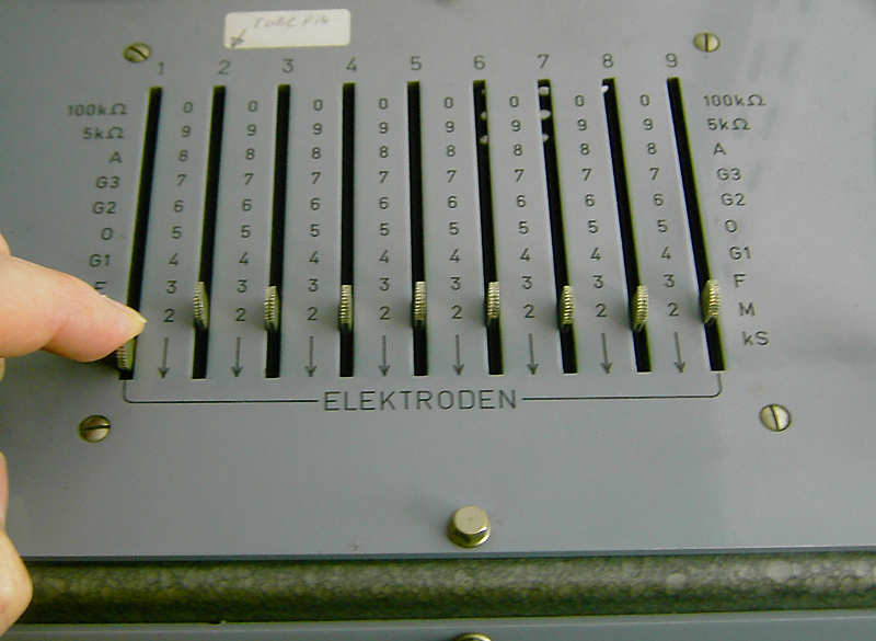
Picture 1. The slide switches of the METRIX U61B. :
So take quick reference data sheet (click here for example) and you can quickly connect and test a random tube, because normal data sheet pin numbering is used here! Before you start you do need to test for shorts and leakage. Here is shown ho that is done. With all switches to "M" as you see in picture1, all pins are connected to ground of the tester.
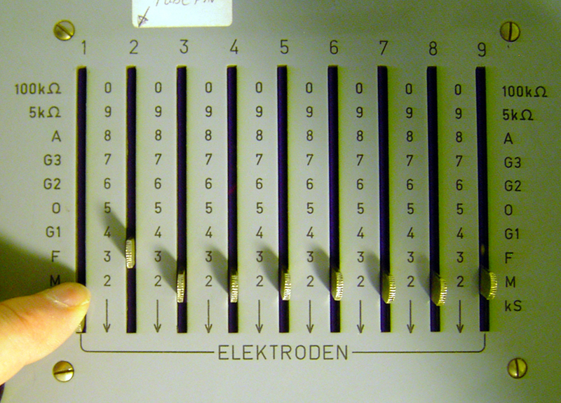
Picture 2. Press each slide down, and see if the neon lamp burns. Function: Shortage or open filament. All tube pins are connected to ground (M) and now you press one by one, each switch to the position "kS". This connects the corresponding tube pin to an AC voltage source, and the neon lamp is placed in series with it. When you let go the slide, it moves back to the M position. When the tube is ok, you find the connections of the filament like this. Suppose the filament is connected to pin2 and pin7. You start to press all slides down, one by one. You press 1, 2, 3, 4, etc. The moment you press slide switch 2, the lamp will burn. That is because switch 7 is connected to "M" (ground) still. Then when you press switch 7, the lamp also burns. So the filament is obviously connected to 2 and 7. This means you have no shortage, because the "shortage" you found between 2+7 is the only one, but this is the filament of course. If there is no connection to be found at all, you have an open filament. If the lamp burns at three positions, you have a shortage. An exception is of course tubes with three filament connections like ECC81. This tube must light up the neon lamp at three positions. So this is a simple, logical and efficient way.
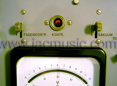
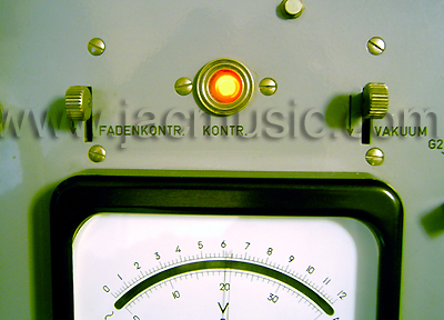
Picture 3. Apply filament voltage. Function: leakage test Assumed there are no shorts in the previous test, and the filament is not open, we continue with the leakage test here. This must be done on a warm tube, because the leakage normally increases when hot, and may even fully disappear when cold. With the tube we have here, we found the filament between pin 2 + 7. To connect the filament transformer to those, pin 2 is connected to "F" and pin 7 is left connected to "M". Between F and ground (M) the filament voltage of the tester is connected. Now the filament will light up, and the neon lamp is off. To double check this, you press the left button from picture Nr. 4. When you press it, the lamp burns, indicating a good filament. So we really know everything is ok. Now let warm up the tube for at least 5 minutes, and then the leakage tests can be done. For this, all slides are pressed one by one, to the "kS" position, apart for the filament connection, which is left at "F". What you might see now, is:
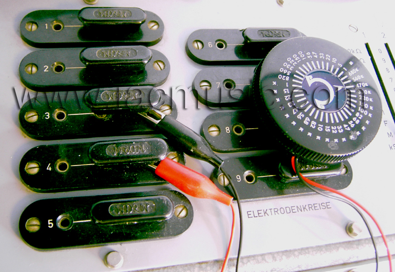
Picture 8. This is how the effects of a leakage resistance was pictured. A variable resistor was connected between pin 3 + 4. So when pushing slide 3 or 4, the lamp would burn. By this we could picture the neon lamp, and say what the leakage resistance was that caused a certain brightness. Conclusion: It works amazingly well, and quick. Do not think this "lamp" method is primitive. You get very reliable results with it. When you use an AVO or any other tester having an analog meter, you will soon notice the meter is insensitive. So if you have a tube that you know has some leakage, you will try to measure the leakage. So you have to say something about a movement of 4 mm on the needle scale. So the scale gives you a number, but what does that number mean to you? Probably nothing, unless you're an ultimate expert of course. What you want to know is the leakage too much or not. It's just yes or no. For that you might just as well have a look at a neon lamp, provided it indicates "good or bad". What is nice about the neon lamp is, that it starts to burn short before the critical area of cathode leakage. (The most important test, because that is the kind of leakage you'll see, and that's the one that causes a tube to hum) A reasonable value for cathode leakage is 470k Ohms. The neon lamps burns at 25% with that value. The beginning of the light effect is at 1Meg Ohm, which is a good tube. Note: You must measure this with a hot filament. With a good tube, you'll measure no leakage when cold, and often some minimal (normal) leakage when hot. Metrix U661 extension unit
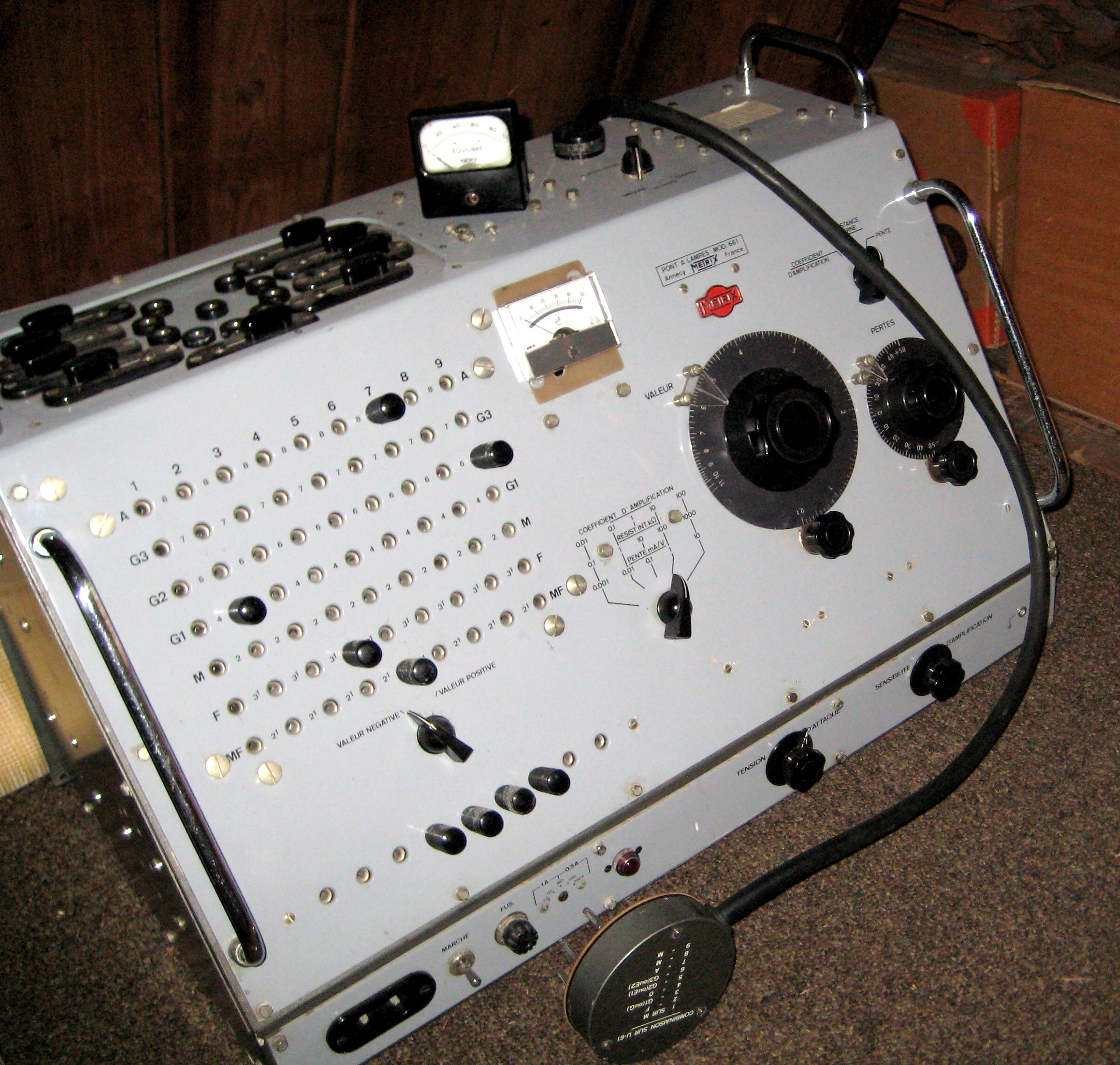
This extension unit makes it possible to test Gain, Transconductance, and Ri. It must be used together with the U61B. It is extremely rare. |


