Use of cards on L1 and L3 tester
Introduction
By making the right kind of cards, even more can be done with these tube testers as originally intended. Such as burn in tubes, tests the tester itself, use it as a lab power supply, including the test oscillator, or use it as an instrument to do leakage tests of various kind.
Safety
It is recommended not to experiment with new settings yourself. The deck with the pins allows for any mistake whatsoever, so a new card must always be checked via the schematic, to see what it does. Also, some of the plug holes have 1000V AC on them, so think twice before you put a plug into those. When plugging or unplugging cards, the tester should be switched off, because the metal of some pins carry a few hundred Volts, and you can easily touch them with the one hand, and the grounded handles with your other. I learned this the hard way myself.
There are five ways to test amplifier tubes.
- Adjustable Bias
- Auto Bias
- Mixed Bias (Combined Adjustable and Auto Bias)
- Emission Test
- Curve Tracing
There are three ways to rectifier tubes.
- Forward voltage testing
- Test the tube in a real rectifier circuit.
- Curve Tracing
Other Parts it can test
With the right cards, other tubes and parts can be tested such as:
- Voltage regulator tubes
- Current regulator tubes. (Urdox tubes)
- Magic eye tubes (we have a card for EM34)
- Thyratrons
- Zener diodes
- Neon Lamps (We have a card for that)
- High Voltage Capacitor leakage
- The tester itself. The switchboard has many connections deep inside.
Other Functions
- Lab Power supply for tube circuit design. Giving 2x High Voltage, 1x Negative Voltage, heater voltage, 1400 Hz test signal from the oscillator.
- Supply a range of AC voltages for circuit design, up to 1000V AC.
- DC nano ampere meter.
- Isolation tester, using 100V DC as test voltage
- Capacitor formatting / Leakage Testing
When you are new with tube testing
First try to focus on the basic tests, and not begin immediately with parametric testing. Autobias testing is easier to do, and results are more meaningful. The Emission Cards (by the Funke W19 method) are the easiest to use, and give a fast answer to the main question:- Must a tube be replaced, or not?
- Is sufficient remaining life time left?
Parametric testing is for other purposes. This method is a major source of mistakes and self invented quality criteria. There is common misunderstanding, tubes at a minimum of 100% plate current, if tested at avarage grid voltage, have the highest emission (i.e. best quality). You really have to digest the previous sentence, and it should not be so difficult to see how wrong it is! This madness goes even so far, a manufacter like Amplitrex calls this result "emission" and expresses it is even in percent. I cannot get it. And they are not the only one making this mistake. So users get presented those adjustable bias tube testers, together with build in tables with tube essentials (avarage data) and have no better idea than to test tubes with fixed grid voltage. Whereas really such results are completely (and I mean completely) useless, because nobody can know the grid voltage tolerance of an unknown tube. Just without knowing how far off a tube is, with grid tolerance, it becomes simply silly when this is igonored, and the tube is tested as if the grid voltage has zero percent tolerance. I think you can do a better job, by trying to find out first, how far off is your tube with grid tolerance anyway?!
I mean if you ignore the grid voltage tolerance, simply do as if it zero, for a random tube, you may as well do as if the plate current has zero percent tolerance as well, and save yourself the whole trouble of testing the tubes at all.
Sorry for putting this is such a context, but I hope it wakes up some people.
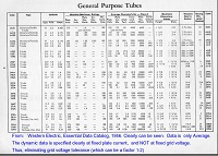
Click on the left image, from the Western Electric Essentials catalog of 1956. Some people refuse 85% plate current tubes, assuming tolerance on the grid voltage is 0%. How silly this requirement is, you can see from the following. Just take random tubes, of which you know they are unused, and from fine brand. Set them all at the same plate current, and now the grid voltage tolerance becomes visible. And you will see, it is large. A factor 1:2 can happen easily. Combine (i.e. multiply...) that percentage with the transconductance and there you have: A wide difference in plate current, sometines 1:2, caused by fully normal grid voltage tolerance, and not by wear out, or tube issues. If this gives you a head ache, that is normal, because parametric testing cannot be used for quality judgement. Take it as a good reason to begin with the right method for quality testing: Auto Bias.
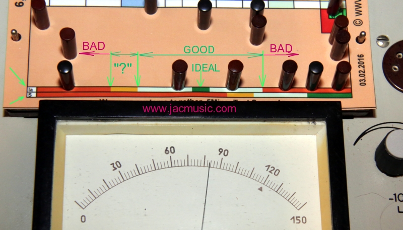
For quick answering of most questions, the cards have a color band.
Possible results can be:
- Bad. (too low)' This tube is a full reject.
- . This may seem unlogical, but it is not. This needs good judgment, but in a practical situation you can say such a tube will play in amplifiers that are not very hard on the tubes.
- IDEAL. This is not so much the ideal value, but rather AVERAGE value of a new tube. However, we need to give a word to it, and it is used elsewhere. Sometimes an ideal tube also called a BOGEY tube. So do not think a not-ideal tube is not so ideal. It may well be. What counts most is a "good" read on auto bias cards. That proves the tube works good in a real circuit (as programmed into this tester), with bias resistor an decoupling capacitor. Whereas the Emission Cards give an indication of the cathode quality only, which test bypasses on purpose all other effects. Which for tube quality, in many cases comes gives the same result, but to really be safe, a tube should pass both tests.
- GOOD: means what it is. It does not mean the tube is unused. Also the question how long it will stay good, is not answered. Practically speaking, a tube needs not to be replaced when it's in the green.
- Bad. (too high). This is also a reject. This indicates usually some damage, like grid deformation. Often caused by drop damage. Such a tube is usually characterized by great lack of transconductance.
Using a tube tester (in general).
This is the most difficult part. Sorry for the long text.
Look at the above meter once more. So we have two 'BAD' ranges, the 'GOOD" range, the 'IDEAL' range and the '?' range.
The best would is, when the initial test values, when the tube was new, is still available. With that data, we directly compare the tube with it's original condition. It would be possible, to use the same grid voltage as at initial tests, and it would be visible if plate current has gone down. Yet, any drop of transconductance tells a lot more about the remaining life time. A compare should be done of course at the same plate current as when the tube was new. This is done by adjusting the grid voltage.
However, the original test results are usually missing. In such a case, we have to compare the tube the datasheet in some sort of a way. It would be a mistake to test the tube at fixed grid (G1) voltage, because the factory tolerance on this parameter is the largest of all. This would distort the picture, and it could even happen that way, a much used tube tests at 115% plate current, which is of course a nonsense result. The same nonsense probably takes place when a tube tests at 85% plate current. In would only NOT be nonsense, when by great coincidence, this tube was testing as a Bogey tube when it was new. Who has ever tested greater quantities of tubes, will know, some 10% are bogey tubes, and the other 90% have either higher or lower plate current. This variation in plate current is caused by grid voltage tolerance.
Are there any good ways to test tubes?
Believe it or not, this is answered in many (not all) tube datasheets. If the test method is not specified, that is not because the manufacturer does not know how to do test his own tubes. It means they do not publish it, in order not to scare off the users.
There are a few ways to deal with tolerance.
- Funke Method. A very elegant way is to eliminate the influences of the grids, by connecting the tube in diode mode. Like this, not only the grid tolerances play no role anymore, but also anode distance tolerance plays almost no role in diode mode. (In triode mode, anode distance is a factor which causes grid voltage tolerance). This method was purified by the Max Funke company in Adenau, Germany. The only thing needed of course is a reliable data base for this, and they had that collected over decades. Link here.
- Fixed plate current. Test at the datasheet average plate current. By this method the grid voltage is adjusted to whatever voltage is takes, to achieve the datasheet average plate current. At this plate current, the transconductance is now tested. This bypasses for a large part any grid voltage tolerance. Any drop in transconductance is now a meaningful number. Link here. Yet this does answer the question if the tube would still bias good in an auto bias circuit. This answer is really very hard to give, other than by using a real auto bias circuit. See the next point for this.
- Auto Bias. There is no point in using a tube any longer, when it doesn't work well in an auto bias circuit, because that is what 98% of the amplifiers are doing. Even so when the amplifier has adjustable bias, but the tube fails in an auto bias test, you may not want to use such a tube anymore. So logically, a real auto bias circuit, is the most meaningful and most important test. Link here. A perfect hand book with auto bias circuits for all tubes, is the AMROH Handbook. Here is a look inside.
- Fixed grid voltage. Just to mention it here. Testing at fixed grid voltage deals in no way with any of the above issues, and results are heavily distorted by tolerance. Generally, this is a wrong, and invalid test method, and you will not find it recommended in datasheets.
Factory tolerance.
There is always the factory tolerance on grid voltage, which tolerance is very high. So if one new tube needs -8Vols in the grid, to draw 10mA, another tube from the same data code may need -11 Volt for that.
When testing large quantities of tubes at fixed (average) grid voltage, this will result for NEW tubes, in anode current variation from 60...140% for USA made tubes, and 70...140% for European tubes, and even so anode current much above 140% is possible.
One may object this is a very high tolerance. Yet this is the reality, and no better tubes were ever made, except some part numbers with datasheet specified, tighter control. This is described in more detail in the "blue book" by Max Funke, who spend most of his life, manufacturing tube testers.
The situation is even worse for new made tubes. The Chinese tubes are often not bad at all, just problematic is, a small part is totally off specs, and limits of 60...150% are touched. The new made Russian tubes, are the winners with tolerance issues, and they have successfully taken away this first place from the Chinese! I do not say Russian tubes are 'bad', it is just you have to prepare for tolerances larger than normal.
Plate current of all brands, factory new tubes, may vary a factor 1:2. So compare parameters of an unknown tube with the average value of the datasheet is totally wrong to do. Since no factory produces only average tubes, you are wrong when you test an unknown tube and blindly compare it to average This is the main mistake, most people make. Even so, makers of new made tube testers feel magically attracted to this mistake as well!
It can not be repeated often enough, there never was a factory specification saying, a tube must comply with average datasheet values. Never!
Even so, RCA even writes in the datasheet of the 6922 tube, you may not test this tube above 5mA, using fixed grid voltage, and you should test it in an auto bias circuit. All you need to do, is read such a data carefully. Recommended datasheets to read are: RCA 6922, Telefunken ECC803S, and Siemens C3g. And no, you will never find a datasheet, telling to test a tube with fixed grid voltage. The only exception is for battery radio tubes, and some other tubes where it can't be done in another way.
So paying extra money tubes testing at average value, is a mistake. Even so, tubes that are above average need to be checked better WHY that is. If such tubes were 'better' by definition, then why did the manufacturers not make all tubes like that?
There is an interesting observation, causes by anode distance tolerance. When plate current is below average, the transconductance is above average, and vice versa. When you see this, you have a tube in front of you with a very strong cathode.
What can pay off, stick a cold tube into a pre-set AVO tester, and watch the speed at which Plate Current rises. I learned this trick in my local radio shop, when I was a kid. The man had an AVO Mk2 Tester on the bench, and it was obvious when a tube woke up faster than others, it is a strong one. For used tubes that takes much longer than for unused tubes. You can compare this of course only for identical tubes. Specially for TV some "fast wake up" types were constructed at a later time. Such as 6SN7 is a normal speed waking up tube, and 6SN7GT is a fast wake up tube.
What remaining life time is left
This is one test method of many. Sorry this tests result can never be in 'hours'.
- Test the tube at first with fixed grid voltage, as on the test card, and check if the plate current is in the green. This is just some initial test. The only requirement is appr 70...140% and then the tube at least is not defective. But that is all it tells you.
- Set it to the 'ideal' plate current now.
- Test if transconductance is in the green. (otherwise you already HAVE a failure now)
- Go back to plate current test, but now set the tube for maximum dissipation. If not possible take at least what the test card allows you. You can increase the dissipation usually very much by increasing the anode voltage.
- At highest allowed dissipation check for leakage and grid current. (Click those links, these are two test sequences)
- If the tube fails at any of the above points, trouble is expected soon, even when it works still
Will the tube be improved by burn in, and do you want to do that?
The Auto Bias cards can be used for burn in conveniently. It is absolutely surprising to see sometimes how much a tube improves after a good burn in. If NOS tubes were stored for 50 years, they may come out if the box, testing "just ok". The weak ones may improve greatly after burn in, and also the spread in parameters will become smaller. Leakage will go away, and transconductance will go up. Note, after already 6 months of storage the tube will begin to loose burn in already. Even factory new tubes are normally not burned in, unless they are SQ types. So what comes out of NOS boxes, many times is initially disappointing. Burn them in first, and then judge again! .
Errorz and Misstakes you can make:
The following is an example of how to test the wrong way. Here done with the AT1000 tester, and a 300B tube. Take the 300B datasheet, and you will see in there: 300V / 60mA at -58V Grid. Transconductance 5600. Ok.... So you set the tester for -58V Grid, and you test the plate current. Suppose it reads 49mA . (not 60mA.) This can be normal factory variation. Now you measure transconductance, and you find not 5600 but 5000, which is only 85% of that.
The (wrong....!!!) result would be:
Plate current 82%, transconductance 85%.
It gets really silly if the test person calls the plate current 'Emission', (or even 'Emissions' suggesting more than one emission), and then we get:
Emission(s) 82%, transconductance 85%. The expensive Amplitrex AT1000 expresses it, in this totally confused and wrong way.
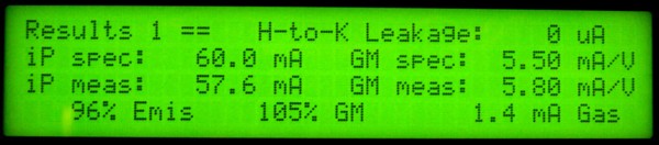
Example of wrong interpretation by Amplitrex AT1000. Suggesting Emission of this tube is 96%
On the other hand, you can make a nice buy on Ebay when you see the seller make this mistake, and there will be not much bidders for such a tube with emission below 100%.
Here is how to do it the right way: You take the 300B datasheet, (or our test card for the L3-3 tester) and you will see in there: '300B tube... 300V / 60mA at -58V Grid voltage. Transconductance 5600'. As a first result you see indeed 49mA. The first conclusion is the tube is good, because that is in the green. Now you want to know: how good?. For that, you adjust the grid voltage such that the plate current becomes 60mA. Now, you measure the transconductance, and here comes the surprise: It is 6100, not 5600.
The (correct....!!!) result for exactly the same tube would be:
Plate current 82%, transconductance 109%
For specialists: Why does one parameter go up and the other goes down? With this tube, it can be concluded this tube has some tolerance of plate-grid distance. If that distance is larger, there will be less anode field gradient. (less Volt per Meter) So you can also say AC feedback is lower, as the anode AC signal field is in opposite phase to the grid signal field, and these fields add up. This lower feedback will make Gm rise. That was for AC. For DC, is another situation. The anode is further away, and the negative DC voltage on the grid will be less affected by the Anode voltage. (Those two fields simply add up, also for the path from grid to cathode). the electron-stopping effect of the grid will become better, and less anode current will flow. So, lower plate current, combined with higher Gm, is nothing but anode geometry, and is not caused by quality of the cathode.