Mains Calibration of a KALIBR L3-3 tube tester
Before you make a measurement, you should set the meter needle on the 'mains calibration' mark. However, you get totally lost, if that internal calibration is out of specs.
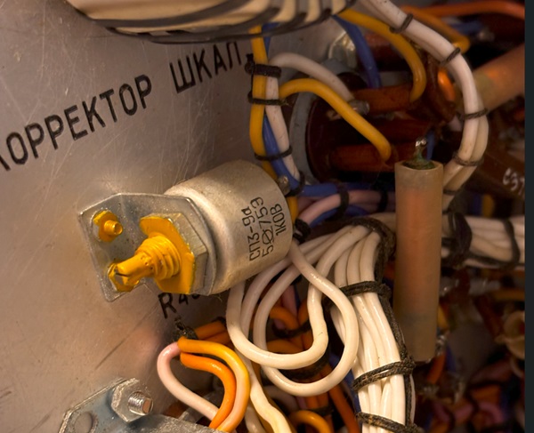
Or, you get also lost, changing this SEALED potmeter for no good reason. DON'T touch it.
I have three L3-3, and the mains calibration mark for all three if them seems factory set for quite some over voltage of the internal voltages. So the tubes were heated with 6.9 Volts, just to give an example. I decided to use the original instruction, of which I use a German translation. It just says: 'set the CAL switch on 7, and then at 220V, the needle must be at the triangle mark. If not, change R85'.
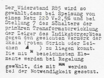
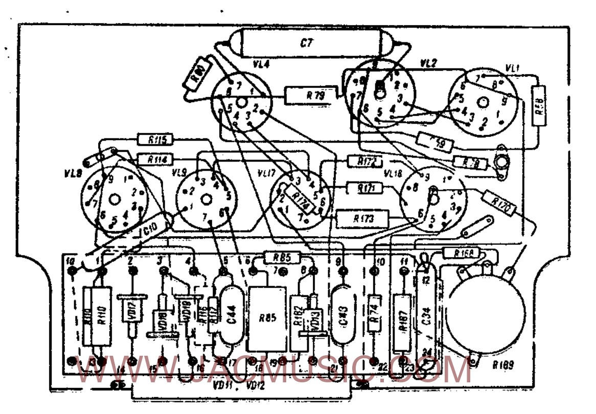
R85 consist of two resistors in series. The large one is a precision type (0.5%) encapsulated. It is 2.4Meg in my tester. The smaller one is 5% type factory selected, it was 360k in my tester. However, when connecting the tester to 220V, and CAL in '7', the meter was much too low. I had to put a resistor of 560k in parallel to the small R85.
Most likely all L3-3 need a new mains calibration, so I pay some attention to this.
Here are my results:
Original condition - Tester in Idle |
After calibration - Tester in Idle |
At 230V. CAL switch was at '7' |
At 230V. CAL switch was at '2' |
Power Consumption in idle 83Watt
|
Power Consumption in idle 74Watt |
Heater voltage for internal tubes: 6.9V |
Heater voltage for internal tubes: 6,45V |
Glow color if the tubes too bright. |
Glow color if the tubes is normal |
Transformer has raw, loud noise |
Transformer has normal, gentle noise |
What I do not understand, each of the two original resistors was not out of specifications. Yet I preferred the original calibration instruction.
SOME PICTURES:
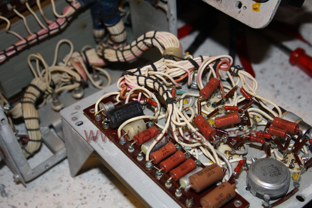
KALIBR L3-3 Tube tester, power Board - Picture 1.
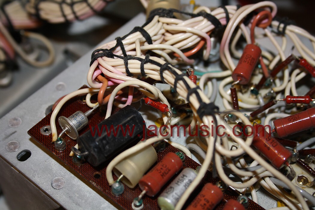
KALIBR L3-3 Tube tester, power Board - Picture 2.
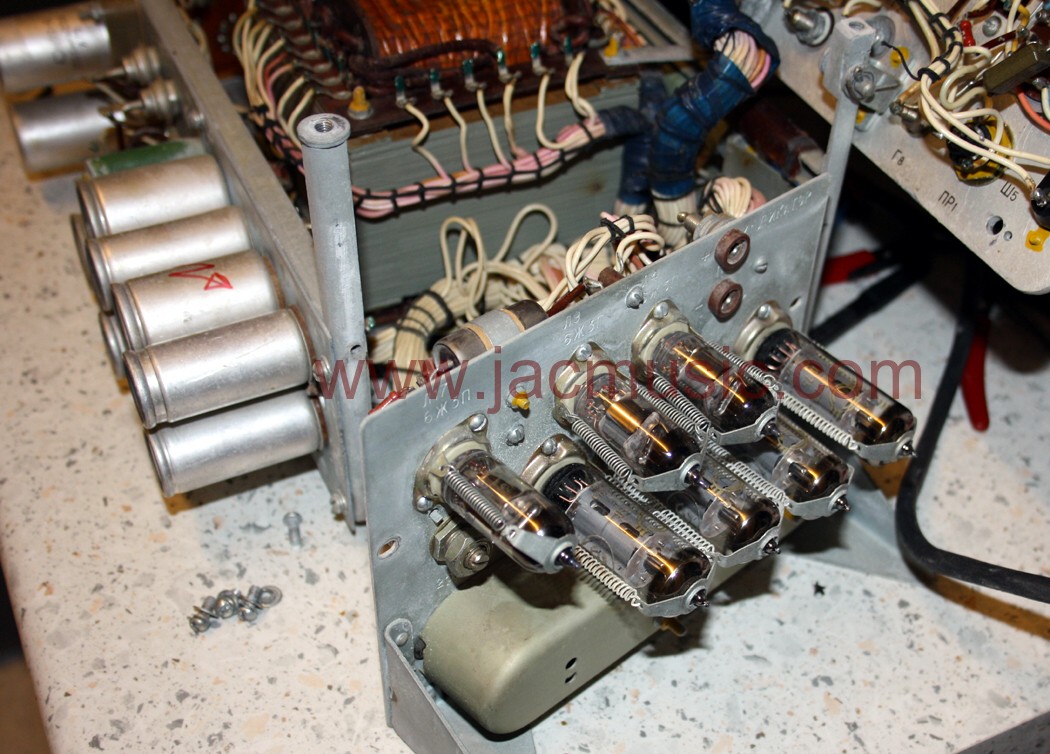
KALIBR L3-3 Tube tester, power Board - Picture 3.
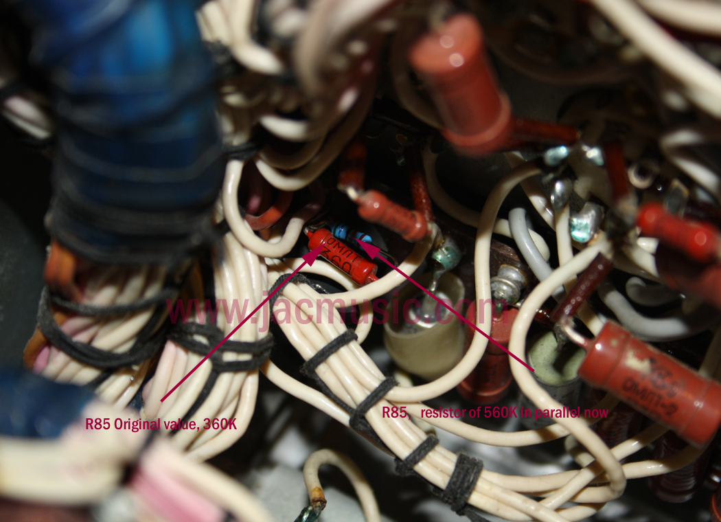
KALIBR L3-3 Tube tester, power Board - Picture 4. Here is is put back in, and a resistor is put in parallel