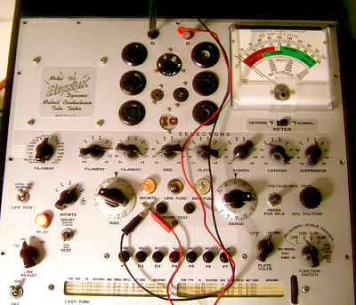
HICKOK 750 restoration project
CALL FOR HELP * * * NEED FACTORY REPAIR MANUAL AND/OR CALIBRATION INSTRUCTIONS * * * HANDBOOK AND SCHEMATIC I HAVE, BUT I NEED THE TECHNICIANS MANUAL. WHAT YOU SEE HERE IS AS FAR AS I GOT WITHOUT IT IF SOMEBODY WANTS TO SHARE THIS INFORMATION BUT KEEP IT PRIVATE FOR THE REST OF IT, OF COUSE THAT IS NO PROBLEM
I bought this tester as "calibrated". Well that was not true, the RANGE (load) potentiometer was not working. The seller send me back some part of the payment, so it was ok for me. We want to get this tester in best possible condition ever, just for the fun of it. Part 1) Meter Calibration
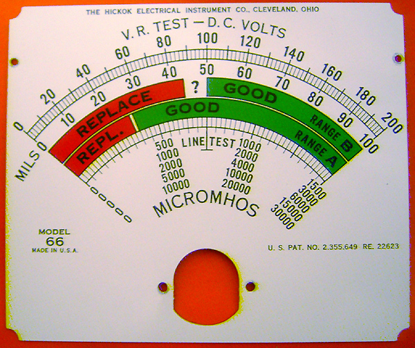
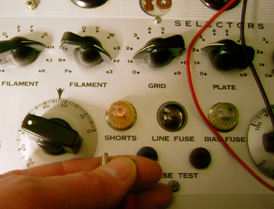
So first thing, first I remove the panel meter, and check it's linearity and full scale sensitivity. Read the Funke W19 project to see what it takes to repair a bad meter, but the Funke W19 meter is a multi meter, so that was a hard one. Most old meters show some deviation here of 3...8% which never disturbed anybody, during the last 50 years or so, but it is going to be a problem for the ultra precise calibration I have in mind here. With the Hickok, this is specially important, since it requires a very precise setting of the line voltage before you begin. The reason why this is so important, is that the tube under test is getting an AC input signal in the grid, which is tapped from the mains transformer. So if the mains voltage is higher or lower, the tube would read higher or lower. For this reason the Hickoks all have primary transformer winding of 93 Volts, and an adjustable series resistor. When this series resistor is set right, the mains transformer has 93Volts, and the tester is accurate. For this, there is a detector circuit inside, and you need to set the meter on the "line test" mark, as seen below.
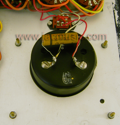
Line Test Mark ( is under the needle now) The meter for this tester is a 280uA Full Scale Hickok meter, type 66. In case you have a problem with the meter itself, and when you are not too much in a hurry, you might be able to dig up another meter, and then just replace the scale. I found the meter didn't have the original sensitivity any more. It needed way over 300uA for full scale. So I opened up the meter, and inside was a series resistor of 450Ohms. It is the typical custom made wire resistor from Hickok, that is found in all the tube testers when a calibration is done with a fixed resistor.
Build in series resistor
So... I had the bright idea to put a small resistor in parallel to the build-in series resistor to increase the meter sensitivity. Much to my surprise, the sensitivity stayed exactly the same. Then I understood the mistake. It is all a series circuit. So I changed the series resistance of the whole meter, and not the full scale sensitivity. Since I didn't want to change the series resistance of the meter, I decided to put it back together again the way it was. I read this before on other web sites too, where they say you can reduce the meter sensitivity, but not increase it. Well, I think they must have had a way for that at Hickok, by doing something with the magnetic gap or so, but I am not going to take the meter apart just to find that out. It is too risky to damage the meter.
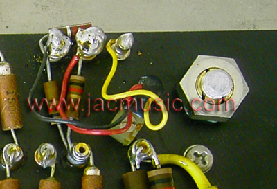
Magnetic shunt Then there was this metal strip, that I wondered what it is for. I thought it was for linearity, but actually it was set all to one side, and linearity was perfect for this meter. Then I found it this is.. a sensitivity control. Later I heard this is called a "magnetic shunt". I set the slide all to the other side, and now sensitivity was a lot better. So I could have left the meter closed. Anyway, now the sensitivity is 296uA for full scale. Still not 280uA, but within range, and I will be able to calibrate all settings nicely like this.
Place vertical, and needle must stay on zero This is an important one, if you are looking for high precision. You need to check the needle balance. For this you set the meter to zero, with the set screw, in horizontal position. The best is to do so with the cover off, so you have no wrong reading caused by static charge (yes sir!). Then repeat in vertical position (as pictured here), and when the reading is the same, your meter needle is balanced, and you don't need to work in this. This is important to check, because the meter is mounted under a small angle. You double check the meter, for 50% scale at half the current, in both positions, and you're done. In case you are interested what needs to be done if this check fails, check with the Funke W19 project. It didn't like to do this at all, but it was the only way to get the Funke W19 meter 100% accurate. Anyway the Hickok Model 66 meter was linear as it is, so I could close it again.
Click on this picture to see the needle balance weights
Warning. The cover of the meter is very static kind of plastic. You can electrostatic charge it very much when you wipe it with a dry cloth, and the air is dry. I found you can get easily a 10° change in angle by this. Really very much, and it surprised me a lot to see this. After a minute or so, all charge is gone, and also when you let the needle move up and down a few times it is gone. You can get severe mistakes if you calibrate it like this. So don't rub the meter panel with a cloth, as I did. I replaced the capacitor over the meter, by a new one. I took a value of 470uF. That is 10x more than original, but that will better protect the meter against the mistakes someone will make some day.
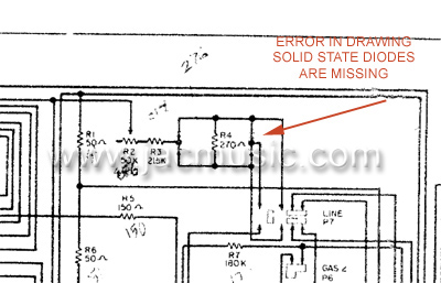
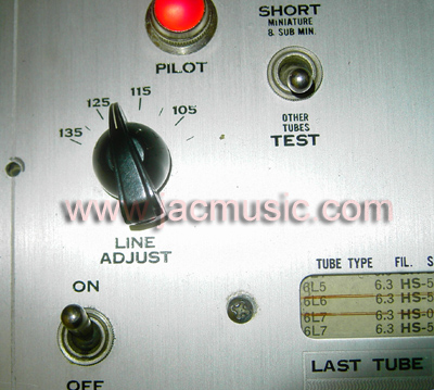
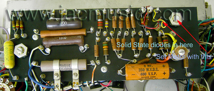
Original capacitor was 50uF We start with the line voltage setting. If there is an error in this one, all other calibration work was for nothing. To set the line voltage, all you do is: plug in a 6L6, and adjust the line voltage potentiometer, such that you get exactly 6.3 Volts filament voltage AT THE SOCKET of the 6L6. So not at the transformer somewhere. When I removed the rectifiers tubes out of the tester, the AC line meter still worked. So there must be solid state diodes somewhere. I think it must be the components with the tiny wires, molded into a housing as used for Germanium transistors. They are not on the drawing. At the drawing is a short circuit drawn across R4, but actually here are the two diodes. (read here too) Part 2) Line voltage Calibration This calibration I show how it's done. All other, please understand this is also my special knowledge and it took me a while to learn this and get the methods and knowledge together. So please understand I can not just copy that here. Still you will see this part is interesting enough!
The actual Line adjust calibration is now very simple: 1. Put in the rectifier tubes in the tester, plug in a 6L6 tube, and check if the filament glows (roll chart settings)
4. On the board below is the potentiometer on the right, release the locking screw.
The mains transformer seems very well designed. This requires a lot of experience of the transformer maker. When you unplug the 6L6, you will see the line test mark is now higher. If you set it down to the line test mark again, you will notice you have exactly 6.3Volt again. So you can be sure the filament voltage is correct, even if the tube draws a lot of current, and will initially drop the filament voltage. Part 3) Calibration of Voltage regulator circuit There is a rectifier circuit in the 750 with the 83 tube, which is switched between the normal transconductance test, and the voltage regulator tube test. In the transconductance test mode, it supplies an AC waveform, which equals 150V effective. In the voltage regulator tube test it supplied real DC 200Volt unloaded. It can be loaded with maximum 100mA, but then the voltage drops at about 150V or so. First, I removed the old electrolytic capacitor that was used in that circuit. (The one you see above, 8mF 350V). It was still good, but to prevent future problems, I replaced it by a Mundorf precision capacitor, self repairing type. So this capacitor will live for ever. You may be tempted to put in a larger value, so the voltage drop is less, but that makes the circuit not short-circuit proof any more. (and it should be so) This circuit is very helpful, for doing other things as just testing voltage regulators. It can test ANYTHING that you put a voltage across, and then want to know the current. Since the internal impedance of the voltage source used, is quite high, you can short circuit this voltage with such a thing as a voltage regulator, but in fact you can also test Zener diodes with it, or anything else.
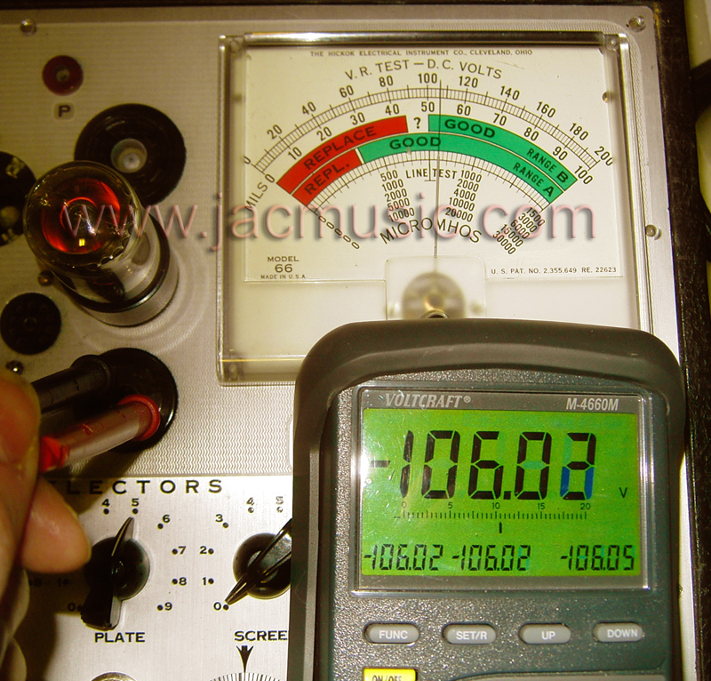
New VR105 tested. It gives exactly 106V at 40mA. Good tube. The settings for the VR105 is as on the roll chart: AP05020. Now when you look at the switches at the tester's deck, you will see they indicate: Cathode at Pin2 and Plate at Pin5. This is what we need, because you can just plug in the meter in the Loctal socket, below the VR105, and measure the voltage there at Pin2 and 5. What you see here, is a VR105 tube under test. The tube is in the top left corner of the picture, you see it glow red. The picture is not to good, but in reality the tube is glowing bright and very nice. This regulator tube will fire at 105V, and from 5...40mA stay within 105...107 Volt. (These can be found NOS, and are great tubes). I found out how to calibrate this voltage, there was no documentation anywhere. It was indicating almost 15% too high on the meter, so completely useless. Well as you see here, it is all corrected now.
Continuous meter test at 40mA. To check the current, you you just set the multi meter to mA, and plug it back in again to the same pins. Of course you short circuit the tube now, it will go out. I regulate down the voltage such that the CURRENT is about 40mA. You shouldn't short circuit it so hard with a milliamp meter at higher values, I am afraid the tester is not made for that. Now as you see this reading is precise, but before I calibrated it, it was 5% off. So that was also done, and now we have a great tool for testing anything, like a rectifier in an alternative way and..... we can repeat all FUNKE W19 measurements. More about this here
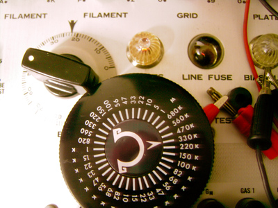
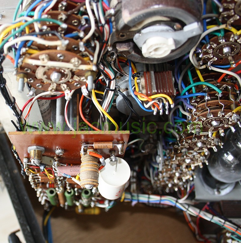
Meter test at 100mA. Next is check the full current capability. This was a real short-circuit test, done at full 200V, and then shunt this voltage with a milliamp meter. It is theoretically possible, so I wanted to know it. I did so only for three seconds, to test the scale after calibration, and as you see it works fine. I am pretty sure, the tester can not withstand this short circuit very long. In reality there will be no such vacuum devices that draw 100mA at only 100mV as the amp meter is doing. So any tube, it will have a certain voltage like 25 volts or more, at 100mA, and then you are safer. Part 4) Repair of "RANGE" (or load) potentiometer Mallory Part Number 16926-4 This is the so called "English" potentiometer. (Don't know why that is....) From what I see in the schematic, not the tube itself is loaded, but the circuit that supplies the plate voltage is loaded by this potentiometer. Well it comes down to the same, but the Hickok method is safer. To make this possible, there are two potentiometers, each loads one half cycle of the rectified voltage. If this potentiometer is broken, you can not replace it by some random potentiometer. It needs to be one with exactly this rotation angle as on the panel dial.
To get this angle exactly right, Hickok had a special potentiometer made at Mallory, which had to possibility to rotate the top deck against the lower deck. You can see in the above picture the offset. Other than what most people think, THIS is what is calibrated, not the value. Since it is a linear wire wound potentiometer, the linearity doesn't change from this. Very clever.
Here you see a the solder joint, which was used the fix the two decks against each other. From the position in the tube tester, and from the variable length connection wire (see picture above) it may well have been possible they calibrated this INSIDE the tester, using he actual scale dial from THIS tester. The solder joint is at the only position you can reach good with a solder iron, after mounting. Now I have been looking at this really good. Another reason why I am believe it was done as I say is that the solder resin traces showed clearly that the potentiometer was with the axis pointing down, when it was sealed. This is an un logic position if you would seal the potentiometer on your work bench. On the picture you can not see the resin any more, but there was a big drop on it before I cleaned it, and the direction it had, conformed this situation. So if you ever have to replace your RANGE potentiometer with another one, you should remove the solder seal, and be able to rotate both halves to each other, and then adapt it exactly to your dial scale. Well, with this one it was not necessary.
It was incredible what dirt was inside the potentiometer, No idea where it came from, because it is reasonable well closed. I have cleaned it first with a liquid to remove the resin. I expect from the seal spot some resin damped inside, and that is dirty stuff for contacts. After that the potentiometer felt scratchy and rough. You could feel metal on metal. It is what I wanted, so now it was clean. Then I cleaned it with another liquid to further remove old grease, and new lubricated it. It was such a big difference after wards! Now it has that nice feeling of a new wire wound potentiometer again. I don't know if this is important, but just for in case someone is interested, I noticed the maximum unbalance of this potentiometer is 5%. There is no way to adjust this, it is the way this one is.
Part 5) Calibration of the Leakage / Shorts test The 750 can not measure leakage directly in ohms, but... it has something also very useful. You can very exactly set the leakage resistance when the short lamps starts to burn. The principle is clever, and it works nice. You just set the shorts dial to 3, and there you go. I calibrated it for 400k Ohms. It works really precise. At 330k Ohms the lamp burns, and at 470 K ohms it goes out. i Another use for this is, you just stick two test probes in the connectors that are normally for the plate cap and grid cap. Plain normal multi meter probes fit in there :) Now you can measure leakage under HIGH VOLTAGE conditions to anything external. So this is not normal leakage you may not be able to detect with a normal multi meter This is tested at about 150V, with very high inner resistance. So you damage nothing.
Official Hickok specs use 200k for this, but I prefer the more critical value, the European testers like Neuberger, etc were using. So I set it for 400k Ohms. You do this with the LEFT potentiometer on the above picture You can even touch the probes with your fingers. The current is so small, you feel almost nothing. The moment you touch the probes, the voltage breaks down, which makes the lamp burn. This is 150 years old technology, and nothing special, but who actually has it readily available in a handy and safe way. Well safe. I hope it is safe. This is by 1950 standards.
Part 6) Quality control (Continued in 2011)
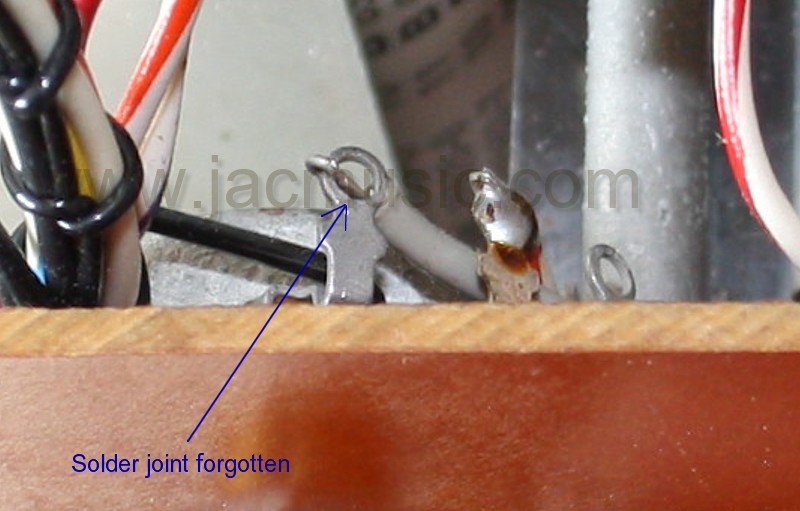
When I as a kid, I used to repair black and white TV's for many years and make some pocket money. It was at the time where large screen B&W TVs were coming, and the smaller screens were disposed when they had a problem, just set on the street, with the household rubbish. Coming from school I took them home on my bicycle, and I had a huge pile of those, trying to fix them. The only tools had was my fathers multi meter, his solder iron, and a tube handbook I bought. Spare tubes I had from other TVs, no schematics, and only rough idea about how a TV works. People threw then away for nothing sometimes. I learned a lot from this, about how to repair an apparatus that you don't kow the details of. First thing you do is, search for catastrophic problems. Such as a broken fuse or a broken tube. The larger part of the problems come from detoriating of the components. Most defective TVs need just one or two small parts replaced and they work again. All you need to do is find those parts. Once I learned that lesson, I went that way, and amazingly I could repair 2/3 of all TV's like this, without knowing how they really worked. Low power carbon resistors can crack. Power resistors can burn, or their value goes up. The larger they are, the more suspected they are. Eletrolytics often are ok, but foil caps are not good any more when they are mounted on a place where some tube or power resistor heats them up. So a VISUAL inspection, I mean a real critical one, usually brings result much faster than any other method. And you see, with such complicated tube testers as the Hickoks, I feel like in the old days again. I take a lens, use good daylight, and visually inspect, and distrust everything. And look here what I found in my Hickok 750. Somebody forgot to solder a wire. It measured the resistance before soldering it. The resistance was zero ohms, so probably this never caused any problems.
|
|---|


