Subscribe or unsubscribe our Mailing List
© COPYRIGHT NOTICE All Rights Reserved.
![]()
BITTORF & FUNKE EINHEITSTESTER
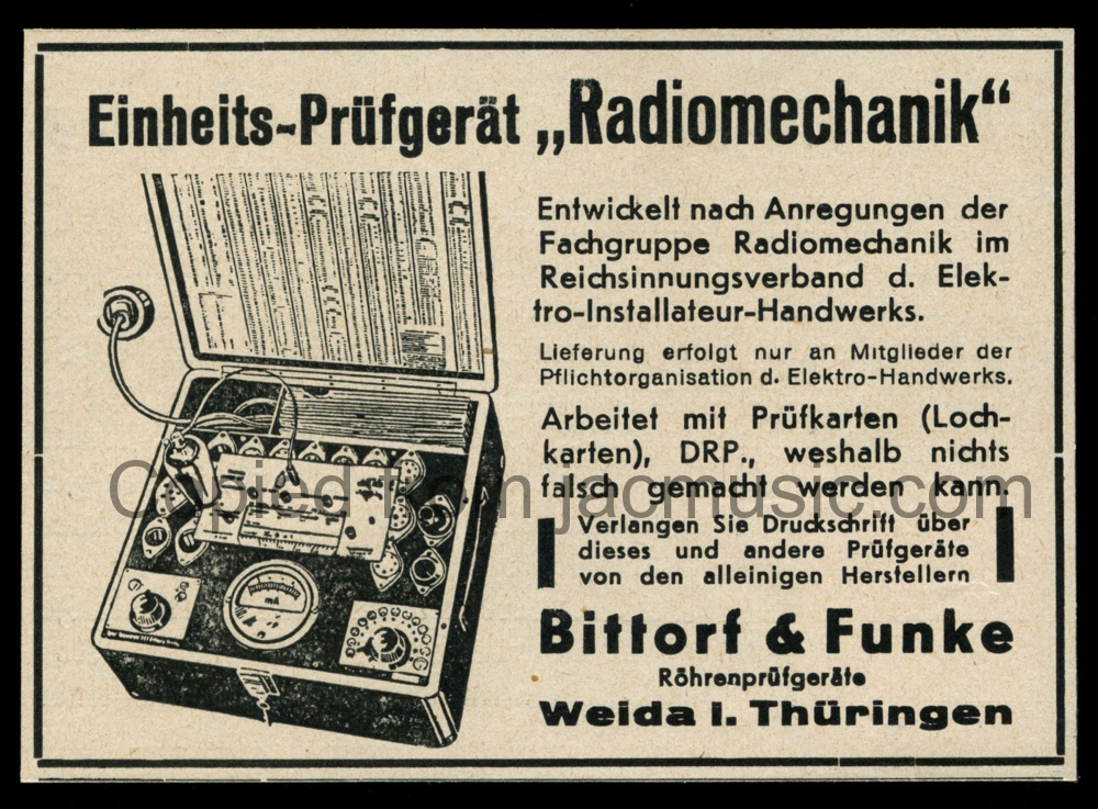
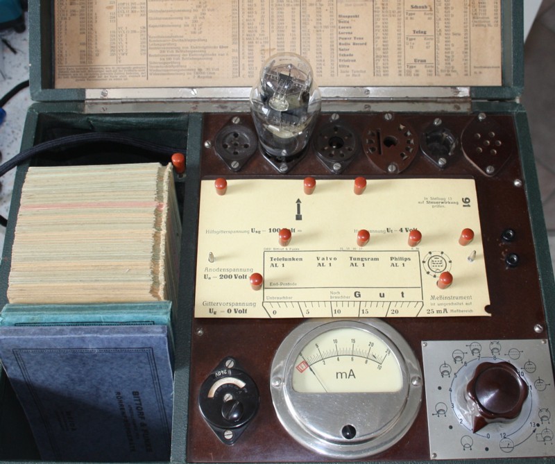
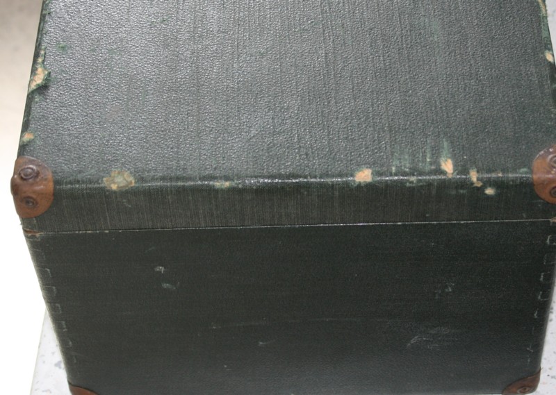
Bittorf & Funke Einheitstester 1949 model
The simple looks, may not make you realize, this is a truly magnificent tester. Test voltage and current is card l programmable, and maximum values are exceptional high. The is the first model of the one-knob testers which works without internal battery, and a stabilized negative grid voltage was generated internally. After this tester came the W16, W18 and W19 which basically work the same, only have more sockets. This tester has received the name "Einheitstester" in English "standard tester" because it had only the European Standard sockets.
THIS TESTER IS IDEAL to make your own tube tester of it, and you can test and tube you like, and easily measure plate current digitally. Check for the drawing at the end of this article. Well people know this, and they are no give away on Ebay, but prices are still reasonable, and the tester is totally easy to understand or repair. Don't be mislead by the simplistic appearance! The device is extremely powerful and amazingly versatile. It can do up to 250mA, and a range of tube stabilized voltages can be selected. It can even test some very powerful tubes at unstabilized AC plate voltage. It's all a matter of the right programming.
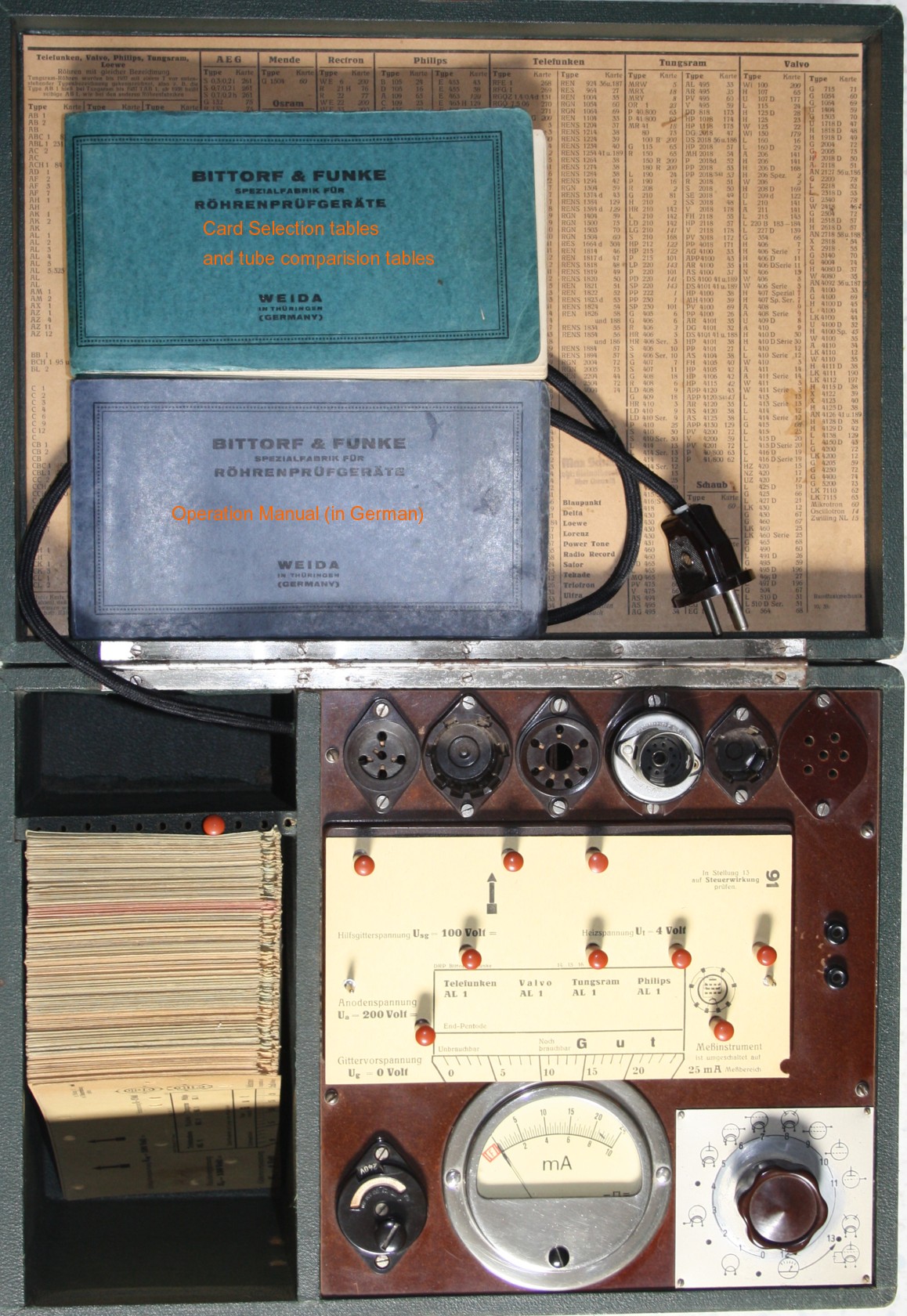
In case you want to expand this tester with more sockets, this is very easy. On position #4 is plugged in a noval adapter socket inside the "Steel tube" socket (adapts tubes like AZ12). A much nicer way is, mount an IEC cable connector to the back. That would give room for three more sockets in the cable compartment, AND you can close the lid while the cable is in the mains still. So in there you might add Octal, 9-pin and 7-pin miniature. To gain more room for more sockets, save the tube books not inside the card compartment. So six more sockets can be added easily, which is probably more than you need anyway.
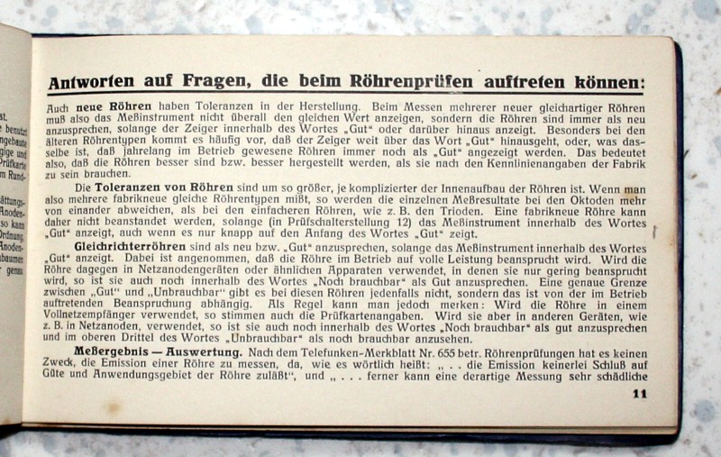
Making new cards for those sockets is easy since on the bakelite cover plate (underneath the card...) all voltages and settings are written. So without card, you can plug it as you like. Then (quote original Funke instructions) you take the most appropriate voltage (EL34 that is Ua= 200Volt Ug2 =150V, but ECC88 Ua= 100 Volt, etc) and you look in the data sheet curves what is the plate current at ZERO Volt grid. Then you set the meter scale such that it indicates this range. For EL34 that is the 100mA scale, for ECC88 that is the 25mA scale. Now Max Funke writes, according to Telefunken Application note 655 (that I do not have for you), the "good" range begins at 70% of this for European tubes and 60% for USA tubes. For this AL4 tube as pictured above the 100% range is 21mA by the data sheet "0 Volt" curve. So the scale of 25mA can be chosen, and "good" begins at 15mA. It is a easy as that! Then connect the tube to the right socket pins, as by the tube data sheet Well there are a few things more you need to look at, but basically this is it. Also look at a corresponding card, how it is made. So above pictured you see a card for a directly heated pentode. If you want to make a card of the "47" which is a USA directly heated pentode, you can borrow most settings from this card to have a quick beginning. Then refine those settings to correspond to the "47" data sheet instead of AL1 as shown here. Like adapt the filament voltage from 4V to 2.5V. etc. Once you have the settings, save them in an Excel table, or overlay a piece of paper on the tester, and plug through the connectors. I have a system like this for my L3-3 Russian tester with Excel which also does the graphics and prints cards even better than the original.
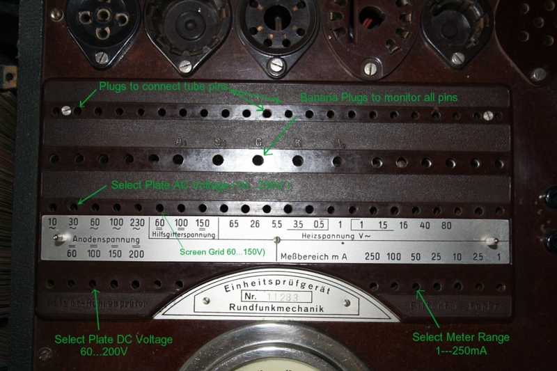
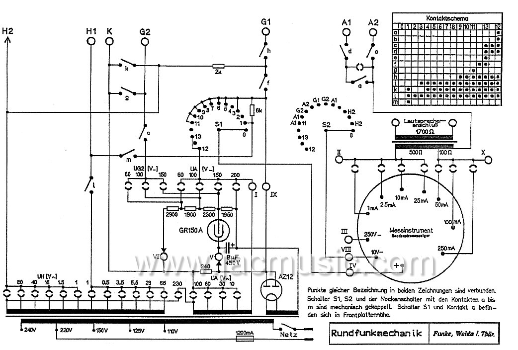
Possibilities for adjustment are shown here
This tester can really do very much. As you can see above:
Plate Voltage AC: 10 - 30 - 60 -100 -230V. This is not only for diodes, but can also be used to test amplifier tubes, same way as a AVO does this, so the tube works only on the positive half of the mains voltage, and rectifies it's own supply voltage that way. The advantage of this method is, the supply voltage for the tube is directly from the AC transformer, which is very strong, and 250mA is possible. Sp at 230V AC that is 57 Watt plate dissipation. Same as with the AVO, effective plate dissipation is only half of it, as the negative half of the cycle is unused. So protection of the tube is good, as heat dissipation is for 125mA, wheras test results are indeed for an effective 250mA.
Plate Voltage DC: 60 - 100 - 150 -200. These voltages are stabilized with the GR150 stabilizer tube, where the 150V is directly from the tube, and a remarkable precise reference voltage. The lower voltages are generated with a resistor divider, so these drop somewhat at higher load. This is no issue, as the cards will anticipate for that, and voltage drop is known, and the same for all testers. So when using the 60V tap, and it would drop to 55V at for instance 75mA, it means only the tube is effectively tested at 55V, and the cards are made for this. Meaning the test result, saying "good begins at" is still fully accurate.
Heater voltages: You can find those out yourself. It begins with 1Volt when you put in the plugs left and right from the number "1". Then, by moving the right plug into the right field, you add up those voltages as written there. Same for the left plug. So almost any voltage, also for over- or under heating experiments, is possible. Just do not put two plugs in the right field, or in the left field, as that would give a short. This is also the case for all other voltages. So before making a card, think good about what you are doing.
Screen grid: 60 - 100 -150Volt DC
Meter full scale: 1 - 2.5 - 10 - 25 -50 -100 - 250. The meter itself is not just a panel meter, it is a calibrated multi meter. So the attenuator network is internally build in the meter, and haven calibrated there by means rubbing off a layer of resistive wires. So you find a collection if wire wound coils in there. For the technician, this makes is totally easy to check the meter, as it has simply connections at the back for: 1mA full scale, 2.5mA full scale, etc. Also this makes the circuit diagram easy and simple, and following from this also the wiring becomes simple. Restoration of the meter is easy also, since in the end all you need to do, is check 1 by 1 the resistors, and you can adjust or verify the meter as a separate unit, on the bench.
What is left, is just a series of plugs to connect the tester to the tube sockets. Here we do have to say, there is a restriction, the selection options is limited to 1 out of 8 pins. So in case you want to add a noval socket, it still can be done, but you may not be able to test any tube with it whatsoever as you can use only 8 out of 9 pins. With all ECC81, 82, etc, this can be solved by connecting the heater to 12.6V and ignore the heater center tap. With ECC88 and similar this can be solved by ignoring the shield connection. So with two noval sockets, you can do 99.9% of all tubes. The Amplitrex AT1000 does it the same way, it saved one relay this way, and this tester is considered "great" by many. Not so much by myself, but I just want to point out this way to overcome having only 8 switches for 9 socket contacts. The Philips side pin connectors have normally the heater connected to the same pins, so with those you need also only 8 switches for the anode, and grids.
Conclusion for the connection board: It can be expanded by the user for many, many tubes. Missing test data? Not at all. This is IDENTICAL to Funke W18 or W19 cards. So making new cards for tubes that were invented later, is no problem, provided you have a photocopy of the W18 or W19 cards. Some sell a pdf DVD on Ebay for a fortune, but as soon as I find a copy for free, I will add it here. There is no copyright on that, the Funke company is closed, and rights have expired.
For some weird tubes, like 6C33 you can also add a socket. This little tester has a very large mains transformer inside, so plate dissipation is no problem, and plate current can be measured up to 250mA. However for the 6C33 filaments I recommend not to abuse the internal transformer, and heater plugs. Better is to wire a 12.6 Volt transformer directly to the tube socket. Then make a card for Triode 1 and another card for Triode 2. Or make a dual card, where you plug in "plug1" for Triode1 and another for Triode 2.
The tester can test also at very high plate dissipation when you use AC plate voltage. You say yikes! AC Voltage? Well remember all AVO and Hickok Testers do so, and these are considered soooo good by everyone. I always says DC testers are the best. It is just the Funke that uses STABILIZED DC voltage normally, and AC Voltage as an option for getting 250V at 250mA. Which old tester can do that...?!!
The meter is very precise and made for Funke. This is not a normal panel meter, it is a multi meter, with it's one connection for each range. So it has a 10mA input, 25 input, 100mA and 250mA. Same for the voltages.
The DC Voltage is stabilized with a 150V Stabilizer tube, and lowe voltages are derived from that with a ladder network. A voltage of 50V can be added to get 200V. Since the transformer load of the 150V stabilizer tube is variable, this 50V is more or less stabilized via that method too. All together the 200V is well stabilized.
Defects and repairs to this particular tester.
I bought it from a radio collector who has stored it 20 years ago, and never used it. Any old tester is always defect, also this one. Though no repair was hard to do, only it was a lot of work.
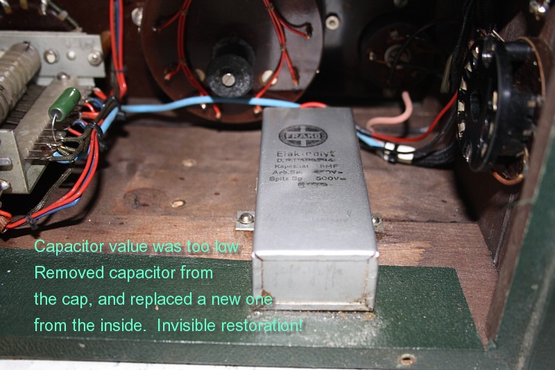
Repairs done are here: mains cable replaced, capacitor re-build, defective resistor replaced, selector switch adjusted and cleaned.
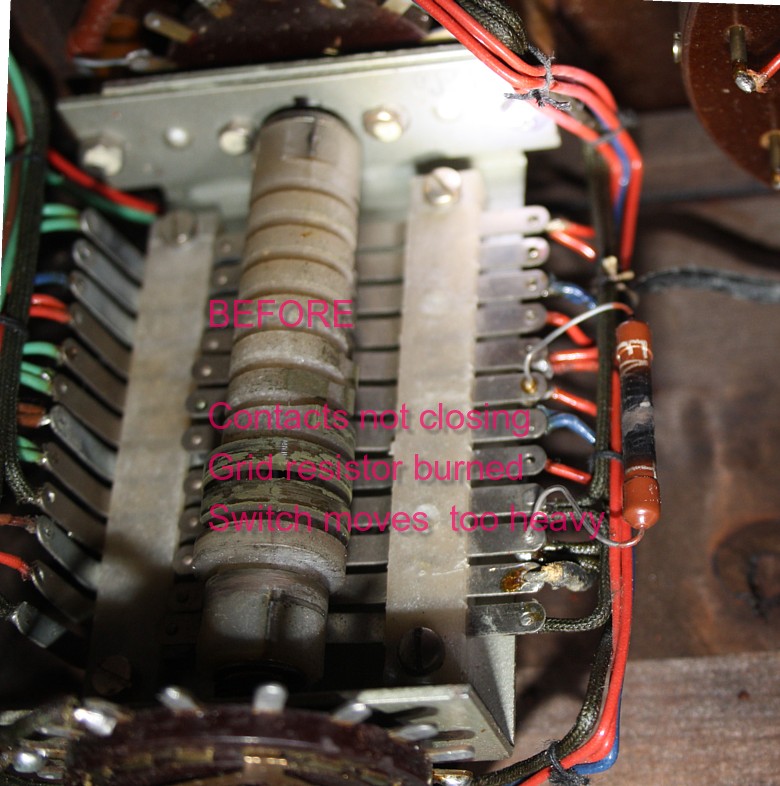
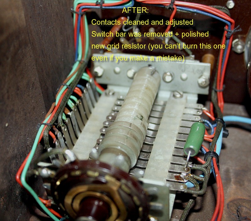
This switch is the center of technical heart of he tester. Though constructed relatively easy, it needs to be taken apart for cleaning, and lubrication. Also contact spring tend to deform over time, and have to be readjusted. All of this was done by me. In the center is an axis which closes and opens the switches the right way, also in the right order, so make before break, and whatever is needed with a particular switch. Some have also a setting in between the positions of the testers deck. Like when going from 6 to 7 there is obviously a setting in between. This must be to prevent wild and current flow, when changing from one measurement to another. It is visible that the switch was adjusted by the factory. I touch nothing unless it is visible there was wear off, from the axis. With this switch I needed only two re-adjustments. I carefully left all other contact distances and closing-break moments unchanged.
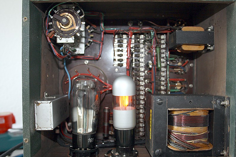
The rectifier tube you see here, it was weak, and was replaced by a NOS tube. WIth the tester is an NOS
Rectifier tube, and an NOS stabilizer tube. The stabilizer is the one on this picture.
View from the inside. Counterclockwise: Selector switch, multi meter bottom, block capacitor, rectifier tube, one of the two ladder resistors, stabilizer tube, mains transformer, some tube sockets, audio output transformer.
Noise check: You can connect a loudspeaker to the banana sockets in the deck, to check for microphonics or scratch noise. This is a normal audio output transformer, the tube under test is now biased in a single ended amplifier at Position 14 at full current, and at position 13 at reduced current. What else do you want :)
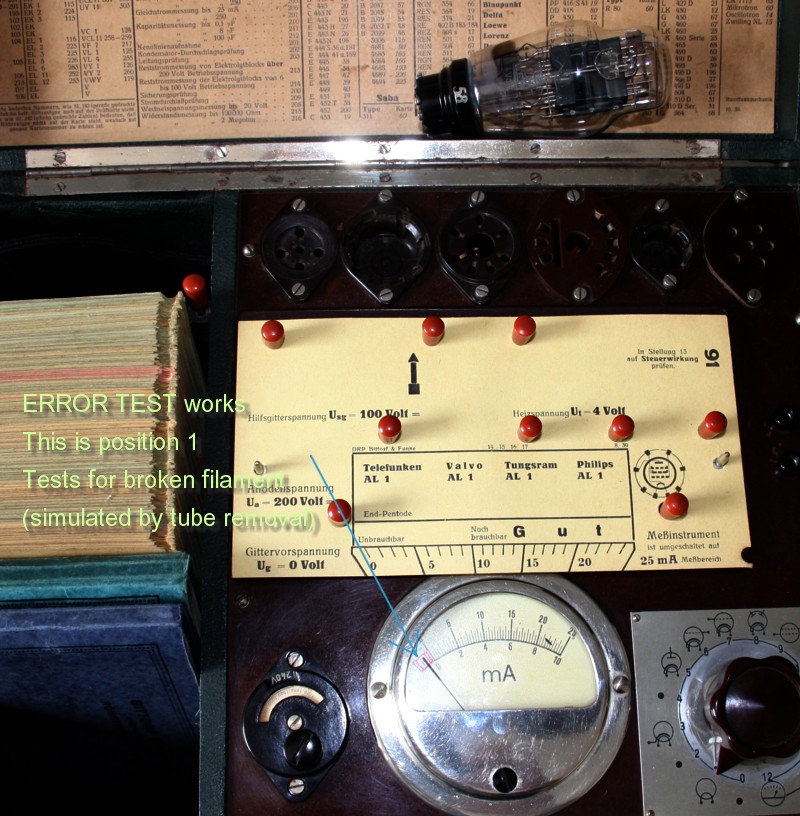
This is the same test as above, so pos1, now with the tube inserted, so the filament is good. (No error indication)
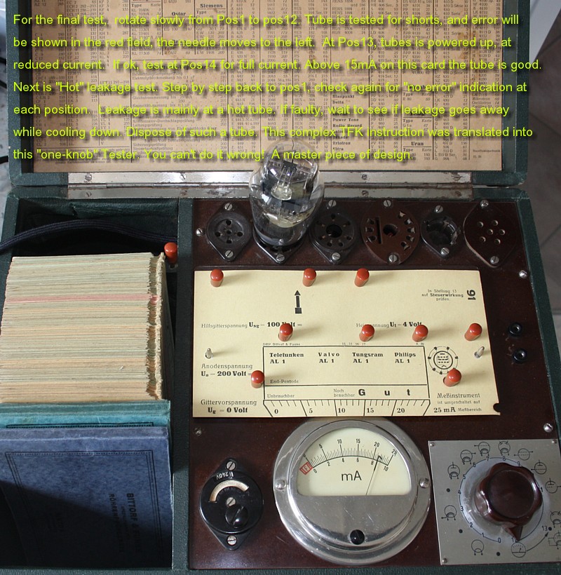
FINAL TEST - TUBE IS PERFECT
Well after 60 years..... it's ok.
This material can still be bought, it is called TOLEX.
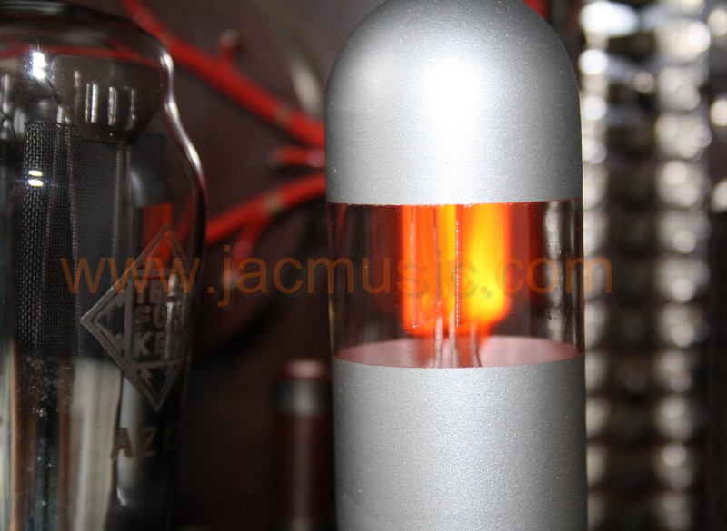
GR150A Rectifier tube.
This is an NOS tube, as originally made for Funke only.
The tube cost by itself 100€. Also the rectifier tube was replaced by a NOS tube.
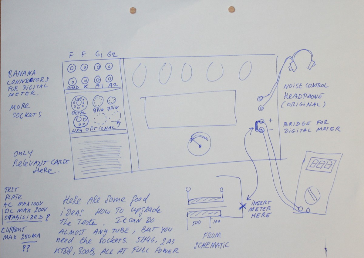
Here are some upgrade ideas for the tester. The headphone is standard, but I would put a an jack plug in it. somewhere else. Then, you can use the original bananas for a digital ampere meter. On the top left is a nice compartment to add banana connectors. Brown for heater. Blue for G1. Green for G2. Red fo A1, Orange for A2 and black for the Cathode. Connect in the schematic above.
Add sockets is easy, when you remove the irrelevant cards, and you free some space that way, in the card compartment. The 9pin socket fails the option to select the 9th pin, the card deck has only an 8 pin matrix, but there are many solutions possible for this, too much to explain here, and in the end you can test almost any noval tube still.
This tester can test tubes at very high voltage or high current. You test tubes at AC or stabilized DC, as you like.
Many settings can be picked from existing tubes, but once you made your first card, you'll find it easier to make your own. For instance 2A3 settings are the same as for AD1, but 2A3 is 2.5V heater. So add a UX4 socket, set the heater to 2.5V and you can test 2A3. KT88 is the same as AL4, but 6.3V. Etc Etc.
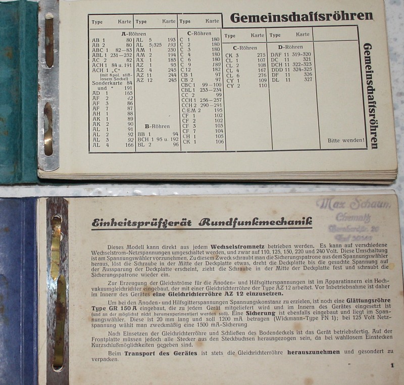
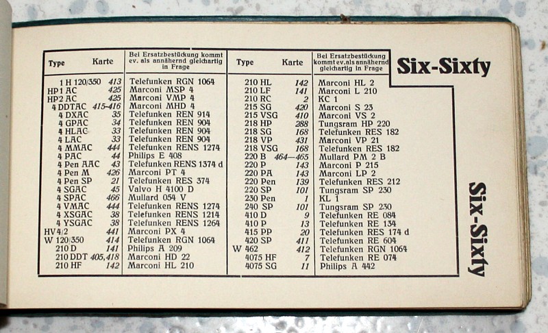
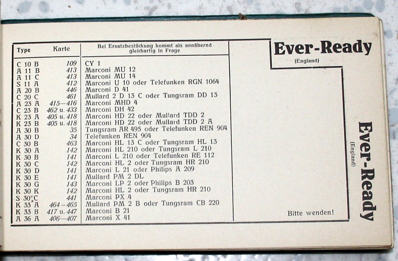
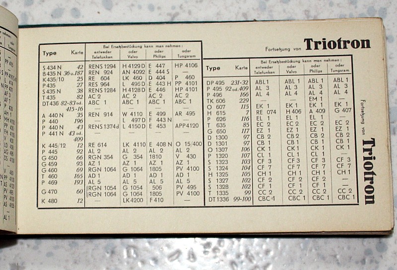
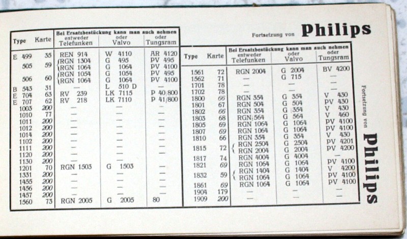
Very interesting is the card selector book, this is a universal Funke book. It gives the cards you need, but also refers to replacement tubes, and actually these replacement tables are the finest I ever saw. It gives information about tubes you never expected. This little book by itself is very valuable if you collect tubes. Did you know you can replace PX4 by a tube called HV4/2 or S30C. Replace RE604 by 420SP, or replace AD1 by a Triotron T460? Set your Ebay search for T460 and wait for an email :)
Subscribe or unsubscribe our Mailing List
© COPYRIGHT NOTICE All Rights Reserved.
![]()