Tube tester calibration
General information about tube tester calibration
Sorry for the large text content... but if you intend to calibrate a tube tester, it is interesting reading ALL of this here, it can save you a lot of trouble.
It is a great help when you know how a particular tester works, and you know what you are doing. Here are some random thoughts, that may be helpful when you are planning a calibration.
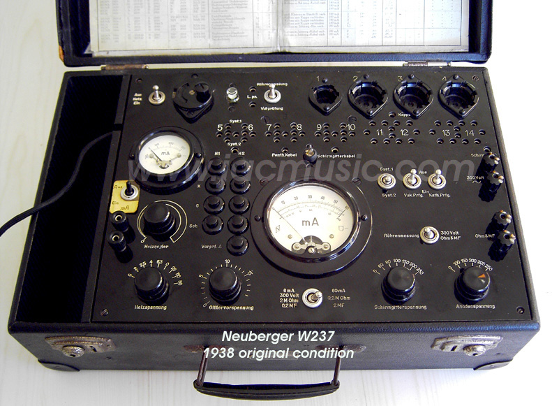
1) Easiest to calibrate are such testers that work with only DC voltages. For instance the Neuberger RPG375, or the Funke testers. There is nothing to calibrate other than what you can see on the meter. So you have knob that gives a variable DC grid voltage, and you read that on a the DC voltmeter. All you do, it test it at 25% scale, 50% and 100%. If all readings are correct, that's it. Anyone who can repair an analog multimeter, can calibrate a tester like this. With such testers, you can get extremely precise results, when the analog meters are top class. And you bet they are with a Neuberger, because they were a meter manufacturer. In this class are also the Funke Testers, and the Russian L3-3. Whereas the L3-3 has additional to the plain DC voltmeter and DC ampere meter some very precise electronics on board like three stabilized power supplies, a tube nano-ampere meter, NF oscillator, band filters, and other things you need to measure transconductance awfully precise. It uses an adjustable, stabilized voltage for the cathode leakage. (The L3-3 separates even tube hum from the NF output signal, so you get no too high Gm reading for a tube that is in fact humming - this can happen to you with a Hickok). But apart from the L3-3, all DC testers are simple construction, and you can see and verify what you are doing. For this category tube testers, all you need is a top class multimeter, that can also measure AC signals precise, up to 2KHz.
2) Relatively easy to service are pure AC tube testers, but most of them are unprecise by default. There is not much to calibrate or to see inside. The problem with those, is often some primitive type of semiconductors, used for rectification of the meter signal. These elements have very strange characteristics, and may not be good anymore. However, the meter scale depends on those. So you can have selenium cells in there or whatever, and nobody can tell you what the forward voltage of those should be. So perhaps they are still ok, and perhaps not. For this category tube testers you need known tubes, and just check the tester with those. Is it off calibration, you can show what good engineer you are.
3) More difficult to work on, are AC tube testers that give true conductance like the Hickoks. Other testers like AVO MK2,3,4 and CT160 give a simulated DC condition, but are in fact all AC testers. For this category tube testers you need a known tube, and inside are potentiometers to make the tester show the correct values. There is NO OTHER WAY to calibrate a Hickok or an AVO than use a precisely known tube. Or a few of t hem, different types.
Note about AVO CT160: It has a reference resistor inside. If this is off-value, you can calibrate it for the 6L6 and get totally wrong readings with ECC88, or vice versa. But also with other testers, it's no good idea only calibrate it only with a 6L6, and then says you're done. At least you need to TRY what it does with a known 6SN7 or 6922..
4) Simple Emission testers on AC voltage These have very few parts inside. For this category tube testers you need known tubes. When the tester is ok - don't touch it. When the tester is giving strange results, simply replace all resistors you see in there with new ones. It is all you can do. If the results are still bad, forger about is, and sell it on Ebay. Many people will think they can repair it.
Generally: If you see carbon resistors that you expect to be precision relevant, don't even think of letting them in. One way is parallel a 10x larger value over that resistor. If the meter doesn't change at all, it's not a value that seems to matter. Never de-solder old resistors to test them. The heat from soldering them back in, can give them the final kick, and you just tested them, and think it was ok. Same for Electrolytic caps, they can be +50 lower or 100% higher. Don't waist your time with those, if you see some, remove them. They can be just "ok" now, and break down tomorrow. These are electro-chemical components, of unknown contents inside. Replace them by foil caps of the same value. (Like Mundorf MCap). These are foil types, same size and voltage as the old electrolytics, but low cost and 3% precision.
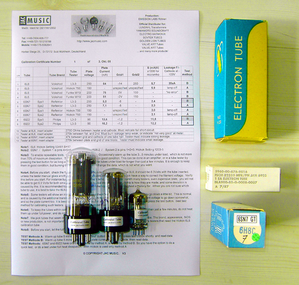
About the Calibration tubes we sell
You may have noticed the transconductance and plate current can go up 10...20% while heating up a tube. Now, one way to calibrate those tubes for you is, take a defined plate current, let it all warm up for 30 minutes, until nothing changes anymore, and measure all tube data like this. Theoretically that works. Only not in reality, because most tube testers do not TELL you the DC current. If they do tell you, it is not the real DC current. So with all AVO's the meter is on 60mA, while there is 30mA flowing. So this is not working out. We go another way, we take a condition you can repeat. We let the tubes warm up on FILAMENT heating only, for 15 minutes. Then we switch on the plate voltage, and measure the plate current and transconductance quickly after each other, and we DON'T wait for the tube to changing parameters due to further heating up. This you can repeat on any tester. So with the Hickok (or AVO) you go just the same way: Let the tube run on filament heater only, for as long as you work on the tester. Then press the "Test" button just very short, and now you do the same as we did, and them you can read on your tester what the transconductance (and plate current) of this tube is. This method repeats on the AVO and any other tester as well.
Before you start, check this:
- Get free documentation from the
- Is the tester set up for the mains voltage: So not a 220V tester plugged in at 230V.
- Put in a 6L6 and check the 6,3Volt filament on the socket, with the tube in. More than 5% off is a problem when you want accuracy.
- Repeat this test with the 6SN7 and be surprised.
- Get the calibration documentation first. The inside of the tester gives no clue to the calibration steps.
- Hickok owners: You can make a set-up with some pieces of wood, so you can turn the tester upside down, with the tubes in.
HICKOK OR AVO
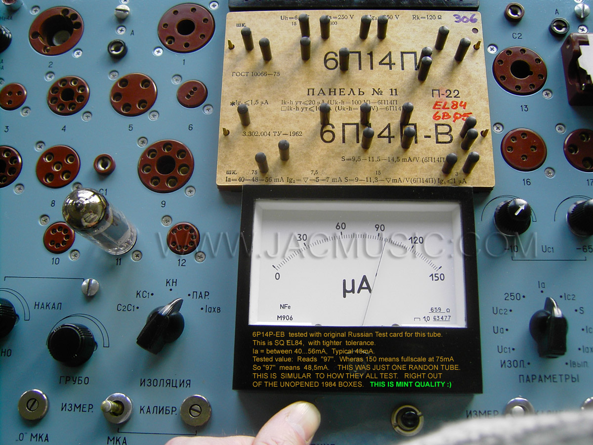
There is no general way to calibrate a Hickok or an AVO, but in most cases in comes down to making the tester indicate a known 6L6 correctly. All models are a bit different. Some Hickoks need soldering in and out t resistors, some AVO's too. Some others AVO's have potentiometers inside for everything, which is nice, you take the reference tube value, and set the scale for correct reading. Procedures for an AVO are set up more logical, and you know better what you are doing, but it in the end it comes down to the same situation: You need a known tube, and adjust the meter to the reading with that tube. Now it is needless to say, if THAT tube is 20% off, your tester is also. Some on Ebay take a "know to be good" Hickok and sell you "know to be good" calibration tubes with that. This is a fraud. And then of course this Hickok was calibrated with another know to be good tube. Hickok kept it a secret how to make such tubes. This is a situation like the chicken or the egg. I believe this is NO GOOD WAY. You don't know what you are getting, and with that you don't know what you're doing. Instead of that, we offer tubes that we know exactly what values they have, and we measured those on a L3-3 parametric tester, not on another Hickok. We have TWO L3-3, all calibrated with NEW Agilent digital equipment. When the tube is tested on the L3-3 with 5700micromho, then you have to adjust you Hickok just for that value.
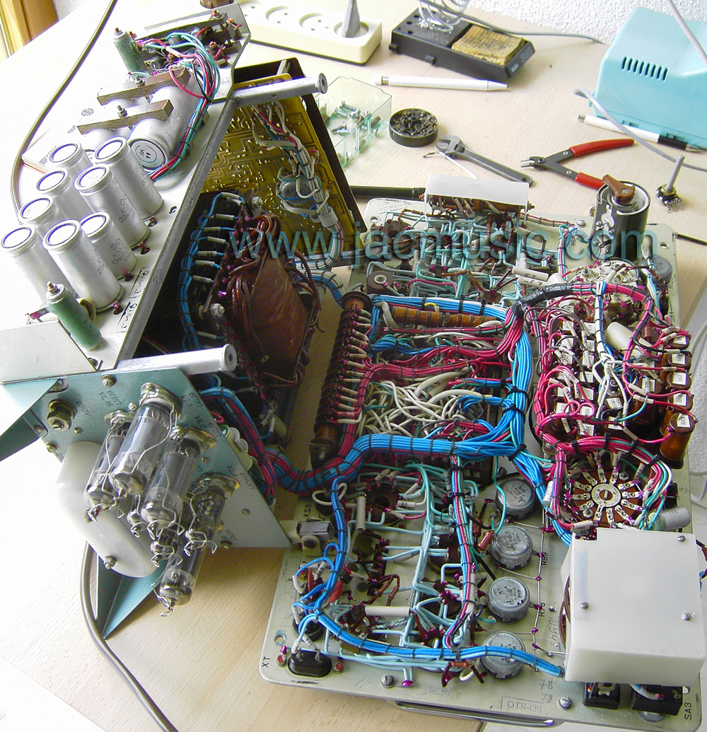 L3-3 opened up for service |
 L3-3 at work. |
|
The Hickoks and AVO's can work really nice, but they have several calibrations inside that need to be done, and when you take care of only one of those, you may not have a good reading for all kind of tubes. What I mean here, suppose you calibrate it for the 6L6, only for micromho scale. In that case it will test all 6L6 nicely on that scale. However, when you put in a 6SN7 you may find a too high reading. But then, if you calibrate it for 6SN7, the 6L6 has a too low reading. If this is the case with your tester, you need to calibrate the bias voltage too, and probably the mains voltage reading also.
So, to see what the condition of your tester is, and if it needs to be worked on, it is recommended to test the tester with some tubes of really know values. That is before you open it up, or do anything at all with it. So these values are undisputable, these are just CORRECT, and if the tester shows something else, it's tester, not those tubes. These are called "calibration tubes".
Here is the challenge: When the tester is good, it gives an accurate readings on all tubes. So that means big tubes, small tubes, triodes and pentodes. Unfortunately, you probably will see that your tester is not as great as you thought, or perhaps you already are aware, are preparing for a calibration round. You are going to see, that the challenge is indeed getting the tester accurate for all sorts of tubes, not just for one type. This can be done, but nut just with one 6L6. So this is why we recommend those three tube types. 6L6, 6SN7 and ECC88.
Emission Testers
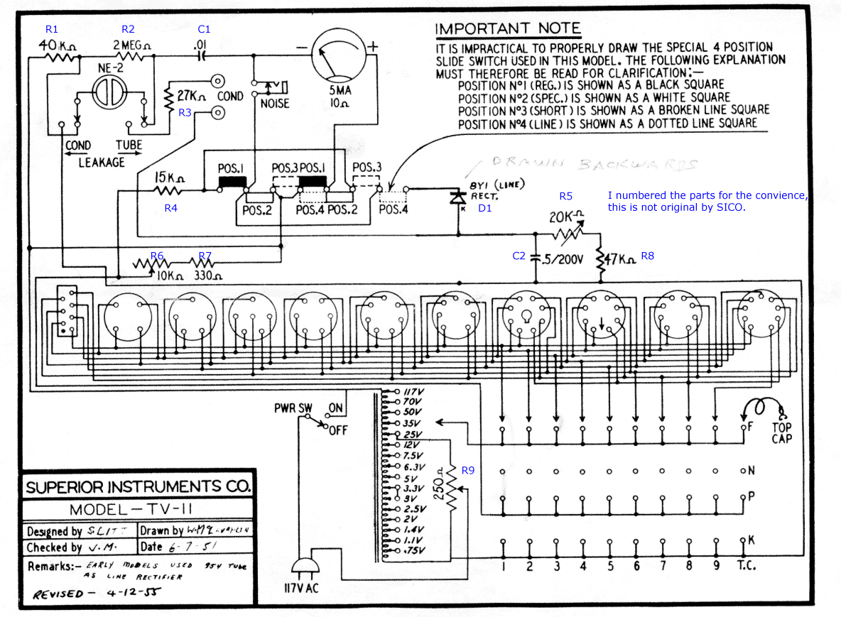
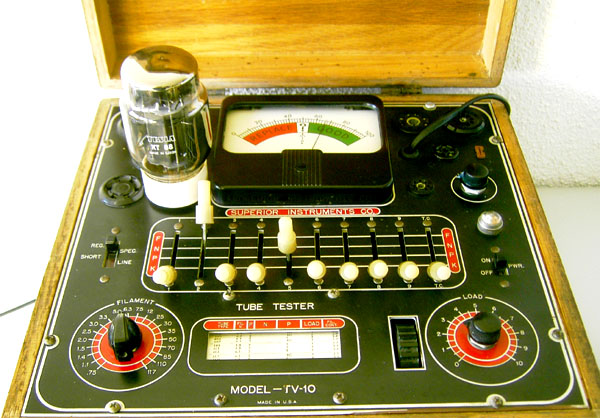 Superior Instruments TV10 (secret tip) |
These are the ones with a row of 10 switches on it. The method here is, that any tube is tested in the diode mode. It is a way to go, and I have found some that are working amazingly well, like for instance the Superior Instruments TV10 or TV11. They look so old fashioned, you would not give much for it. However, they have all modern sockets, even a subminiature socket. They have a quite complete roll chart, plus a calibration potentiometer for the mains voltage. The rectifier for the meter is a tube with the TV10, and solid state for the TV11. It means you have to pay some attention to the TV10's and TV11 rectifier circuit, which measures the mains voltage. The TV10 and TV11 separate the bad tubes from the good ones in a reliable way, and leakage test is working very good. (lamp must go one below 300...400k Ohms). The wooden case is solid oak wood, which can be restored very nice. On the other hand, the wonderful looking (Japanese made!) Lafayette, and TC2, and a few more of similar make, these don't even have a roll chart, and seem to let bad tubes pass to easily. So we'll just say some Emission Testers can be really good, but sure not all of them. Still for this kind of tester, the calibrated tubes we have, make sense. We recommend you to test those tubes under normal conditions, and you should get the needle like in the middle of the green scale or higher. Then reduce the filament voltage from 6.3V to 5V and that should give a much lower reading. If the tubes show no sign of weakness now, the tester is not even detecting this. Sell it on Ebay, and put in a tube which makes it read much in the green. People love to see that, and will pay a good price for it.
Calibration instructions: Set the potentiometer until the rated voltages appear on the transformer, as indicated on the schematic, and then adjust the resistor of the calibration circuit, such that the needle is on the calibration mark. Now check the values of all other resistors. When they are off value, replace them, and you're done).
A warning if you intend to get yourself a TV10 or TV11. This is a simple but good tester. They have an auto transformer inside, so they have a hot chassis. If you connect those to 230V with a 115V to 230 auto transformer as well, you have a "hot" chassis with 230V on it. Combine that with 60 year old wiring, and you have a crazy and very dangerous situation. Since any small wire can get loose, and touch the deck plate. So always modify those with a separation transformer inside (we sell real good ones, from Lundahl), and always connect a three wire mains cable to it, with a ground wire to the deck plate.
Funke W19
These have a stabilized power supply inside, and are in one word: an instrument. We test the 6L6 also on the Funke W19, and give the two readings (high and low one) From the difference you cannot calculate the transconductance, since that's done at Zero grid voltage. However, your Funke W19 must reproduce these DC values still. Let the tube warm up! You must measure after minimum 5 minutes.
Funke W20, Russian L3-3, Neuberger testers.
For those, just use the normal calibration tubes we have, and simply verify if the readings we say these tubes have, reproduce on your test results.