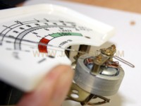
AVO Mk4 tube tester restore project(s)
The first generation tube testers, by the AVO Coil Winders company was the Mk1, which gives only the transconductance. Though perhaps seen by some as "old" it was a masterpiece, and produces surprizingly accurate results, even today with any tube you can find. Also it set the path for the the Mk2. Many featueres of the Mk2 were already found in the Mk1 such as the patented dials to select the tube pins connections. Still the Mk2 is not a second generation Mk1. The working principle of the Mk2 is completely different, and you must see of the Mk2 as the first generation Mk4.
With all following testers, with exception of the CT160, they used a special, patented formula allowing to test a tube completely with AC signals, but get results as if the tube was tested with all DC signals. So don't be confused, you see for instance on the dials a tube is set for 300V plate, and -20V grid, and you see 50mA DC Plate current on the meter, yet the tube is used with all AC signals, and voltage and curent levels are completely different. The meter is producing an avarage result of some wave shape, as produced by the tube which is conducting of course only during the posotive cycle, but still cut off even for some percentage of this cycle. However the meter scale is in DC mA still. Will this work?? Continue reading!
There is no explanation by AVO as to how this works and why. The just say the formula is: following:
Grid Voltage:
Calibrate the dial wheel such that an AC voltage is generated corresponding with 0,52x the value on the dial wheel, then half wave rectify this and apply it to the tube. So for -10Volt Dc grid voltage, you need to use -5.2V AC, and half wave rectify it. So the peak value is 0,74V
Plate and Screen Voltage:
Generate ab AC voltage which is 110% of the DC number you are referring to, half wave rectify this and apply it to the tube. So the peak value is 282V.
This produces a pulsed plate current, of non sinusoidal wave shape.
Plate Current:
Use an moving Coil meter, and calibrate it such that it represents 2x the average value of the AC signal. So if AC is 50mA average, the needle says: 100mA DC.
Calibration:
Then all in the end you take the tester with all parts within the specs, calibrate it with a known tube of the type 12AU7 or 6SN7, and then it will be accurate of all other tubes as well.
In a few words, this is the AVO Patent. The formula is based on the avaraging effect of the panel meter. So the needle and coil have some mass, and the position it takes gainst the coil spring force, is the electrical avarage. AVO repeats t throughout the service manual, that the precision of some of the resistors must be very high. Also the mains calibration must be done very precise. (that is the "cal mains" mark on the meter). My learning curve was, it is NOT possible to "calibrate away" any internal problems inside the tester. If you do, you will find a 6SN7 calibrated well only close to that particular point you took. Any other operating point will be wrong still, and when you take another tube type, you get even larger errors.
PROJECTS |
|
|---|---|
 |
|
 |
|