|
This is a about a restoration project of an AVO CT160. Here is how to use the AVO CT160 I am sorry, it is sold, but you still may find the this helpfull for your own projects. Just bought another one in very nice condition. Little use on it, not worked on by amateurs, a very clean deck, and perfect meter. It needs a repairs on the grid voltage potentiometer, and the transconductance clockwork, which is sort of normal with CT160 after 40 years. For the rest there is nothing wrong with it. After these repairs it needs full calibration, and then it's ready for a long use period again. I need to do this in between normal work. I expected it to be ready for sales by Oct/Dec 2007. It will cost 1600 Euro, add 19% tax when sold in Europe. It will be 100% checked + full calibration done + guaranteed to have no defect or problem whatsoever.
With it comes a copy of the factory calibration
instructions, and a copy of the advanced
Additional is a copy of the CT160 manual, in
a binder. This
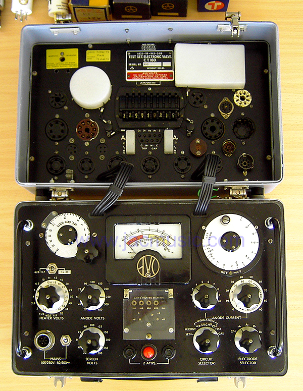
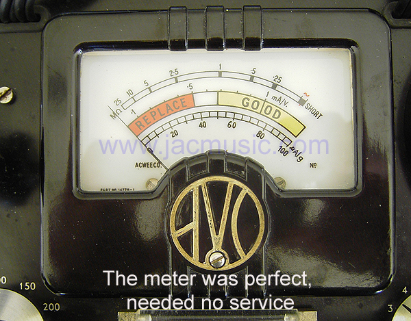
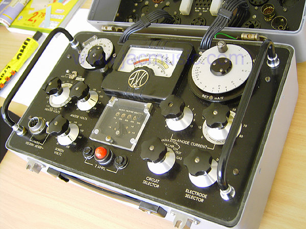
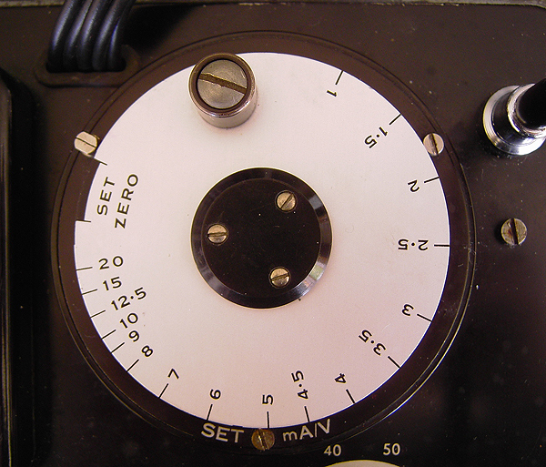
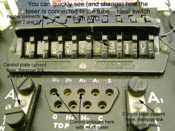
This is one of the finest testers ever made. It competes with the Mk4 in terms of quality and the period when it was made. I agree the Mk4 looks nicer, but I think the CT160 is better. It works by some principles making it more robust than a Mk4, and actually gives a more precise reading at higher current. Sorry for the nice looks of the Mk4, but precision comes first with me. So I prefer the CT160. For instance when you test with a Mk4 on the 100mA scale, you have to estimate the value's second digit. Also with the Mk4 you depend too much on the calibration ( is it still good...?) . With the CT160 you only balance the bridge, and the precision comes from the build in bridge. So with the Mk4, when you read 53mA the 5 is sure, the 3 you must estimate from the scale. It might as well be 52 or 54mA depending on how much you trust what you see. More precision is not possible. With the CT160 you can READ the first and second digit, each on a separate knob, and then estimate the third digit! Because these knobs are part of a bridge, you can't go wrong with what you read. That is why the CT160 has three digits accuracy, instead of two digits with a Mk2, Mk3 or Mk4. You have to check the picture above, where you see two knows with "anode current" written under it. You can see the right is set at 50mA in the picture. The left is between 3 and 4mA. So you are above 53mA and below 54mA for sure. The third digit is the estimation. The left knob is on this case is half way between 3 and 4. That would be 53.5mA when it is exactly half way. When we assume that the accuracy of this estimation is 0,2mA we get an actual reading of 53,4....53.6mA. You can never do that on a Mk4.
HOW DOES THE CT160 WORK?
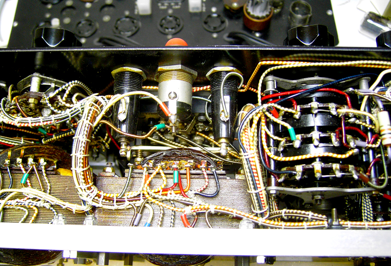
As with most (good!) military testers, it is made fool proof, and works fool proof. So you can make no damaging mistakes easily, and with little efforts, you can get precise results out of it. I think this instrument was an overkill for the army. For engineers, it can measure plate current, Transconductance, and draw tube curves with an XY writer by opening the plate current link and put the XY writer in there. So if the bridge is set to zero (the needle is at zero) you can read Gm and at the same time (!) read the DC current from the plate current knobs (or connect an external mA if you want). For non-technicians there is a setting that produces a good/bad reading too. It can measure all kind of leakage, with the heater on or off. Any way you want. Of course it has a vacuum test too, that can be calibrated. Very short explanation: It has a Wheatstone bridge inside. The left side is a known tube and a known resistor. The known tube is inside, and the only tube it has. The rest is solid state. The right side of the bridge has a known resistor and the tube under test. So the bridge output is connected to the panel meter, and you have to zero the meter. You can either zero it with a given grid voltage, and change the plate current until the bridge balances, OR you can zero it with a given plate current, and read the grid voltage from the bridge potentiometer. The last is very nice, and very protective for the tube. I have seen this on no other tester than the AVO. Now, once the bridge is balanced, and you can read plate current and grid voltage from it, you are going to off-balance it with a know voltage. The off-balance is read on the meter, and is directly the Transconductance It is a bit unusual when you do it for the first time, but it works nice and quick, and amazingly precise. So you can measure Transconductance at any working point YOU choose. Lets be honest, which tester can do that?! All Hickock just say: this is the Transconductance, and say nothing about the working point. With the AVO it tells you the working point, and you can change it. Or just take the manual and take the standard recommendation for the tube under test. So check at what plate current you should test Transconductance, and what the corresponding grid voltage is supposed to be. Read Transconductance directly in mA/V, and know what you have. For the military dummies there is also the option to read Transconductance on the good-bad scale. Both can be done. For the last test, the tester is adjusted for each tube so the "good" scale start exactly where is has to start for a certain tube. Rectifier testing is a book for itself, and many testers test "something" which tells you something about the condition of the tubes. But... what is it you want to know? The AVO CT160 is really straight forwarded with that. It simply plugs in the tube under test in a real rectifier circuit, and them when you set it at 120mA, it expects 120mA rectified DC current from the rectifier. Now this is for me the only real way to test a rectifier. So the way this works is this: You take any rectifier, and rotate the knob through 1,5, 15, 30, 60, 120mA. When the needle come in the green, the rectifier is actually supplying that current. So a 60mA tube must test in the "green" area at 1,5, 15, 30 and 60mA, but not necessarily at 120mA. Then the tube is OK. With big tubes at 120mA the load resistor gets very hot, so test it not too long. Don't use that setting to burn in tubes. With all those excellent possibilities, for me the CT160 is better than the famous Mk4, because the CT160 accuracy comes from the resistor decades in the bridge. With the Mk4 the accuracy comes from a potentiometer scale. We all know a decade bank gives a better reading than a potentiometer scale. So the Mk4 has a more convenient way to measure plate current, but at the cost of less precision. When you know the Mk4 is an AC tester.... no DC signals are used.... then you quickly start to prefer the CT160. My conclusion: The CT160 is the BEST tester AVO made. Only the Mk2/3/4 look nicer, but it these don't work as good as the CT160.
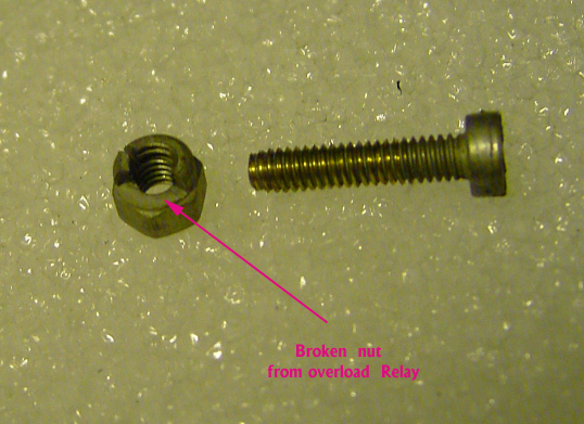
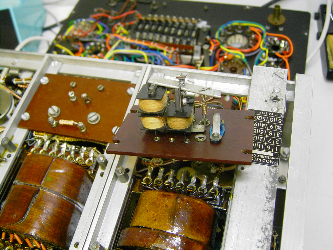
Here are the repairs done to this tester: The overload relay just actives
itself sometimes for no reason, and when you tap on the case, the
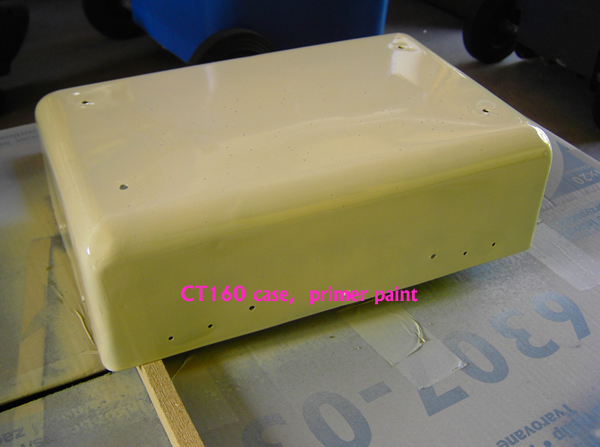
needle would jump up and down 1/3 of the scale. It needed new paint.
The base material was very nice, and not repaired to death by previous
owners. It was all in original condition, and apparently was serviced.
Switches were clean, etc. Just the previous owner did not notice
the problems came from the bad potentiometers. Now read this:
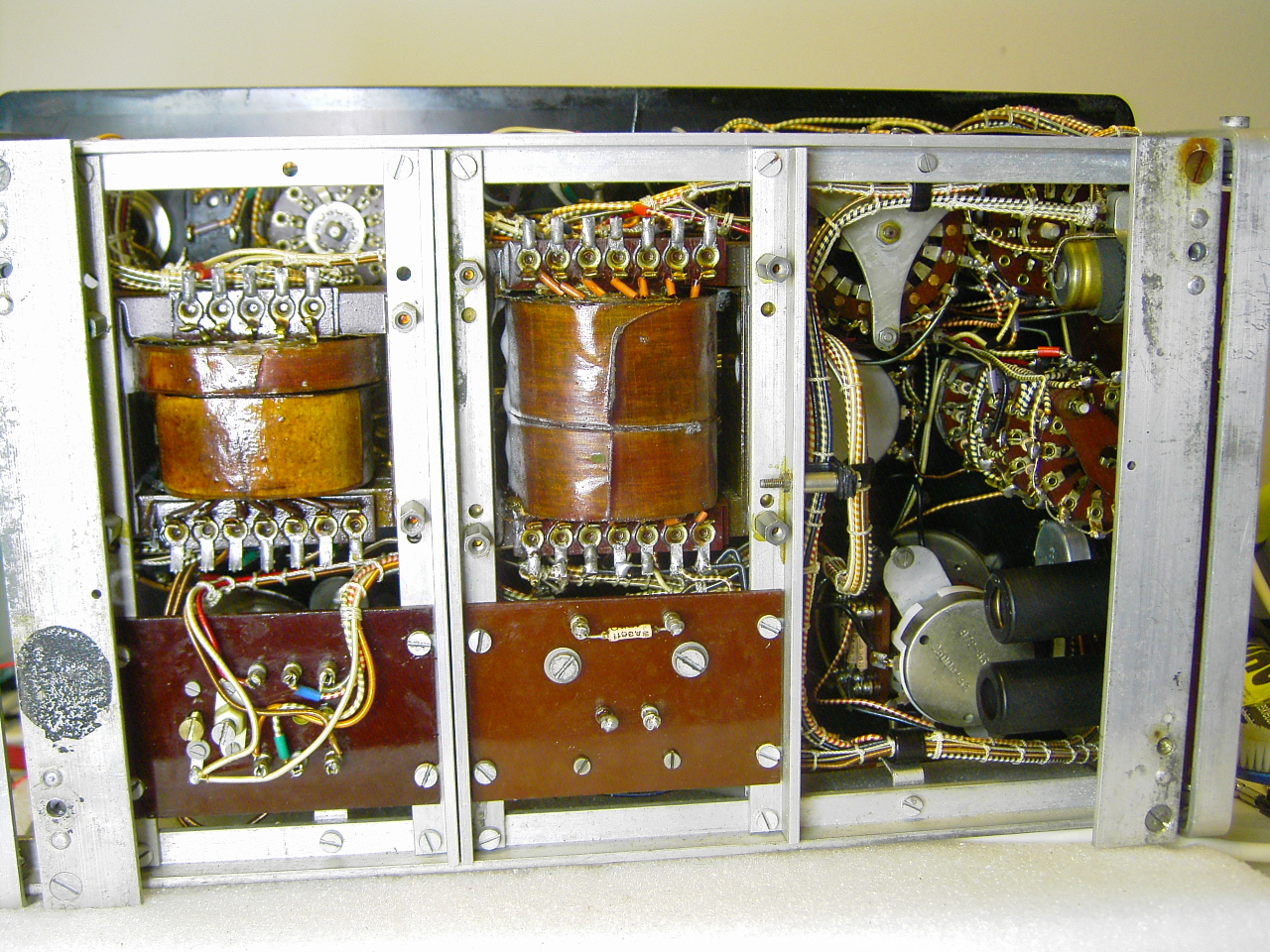
Underneath the cover plate, I found a stash of pretty rare tubes, carefully
packed in plastic wrappings. What a strange place to store tubes...
but OK., I gladly accepted those. It made my day :)
So it was owned by someone who must have loved this instrument.
So because I had a good feeling about that, I decided to do the extra
work and restore it. What was done was this:
|